Employing Camera
This comprehensive guide outlines integration methods for SENSING GMSL cameras across various platforms and systems.
NVIDIA Platform Integration
SENSING provides pre-adapted solutions for NVIDIA platforms, ensuring optimal performance and reliability with minimal integration effort.
Available Solutions
- NVIDIA Jetson Series: Compatible with Jetson AGX Orin, Jetson NX, and Jetson Nano
- NVIDIA DRIVE Series: Compatible with DRIVE AGX Orin
Technical Specifications
| Feature | Specification |
|---|---|
| Interface | GMSL2/GMSL |
| Data Rate | Up to 6Gbps per lane |
| Temperature | -40°C to +85°C |
| Power Supply | 12V DC |
Integration Process
1. Hardware Setup
- Connect cameras to the GMSL interface ports
- Ensure proper power connection (12V DC)
- Verify physical connections and signal integrity
2. Software Configuration
- Install NVIDIA drivers and SDK components
- Configure camera parameters through provided utilities
- Verify image acquisition and quality
Documentation & Resources
NVIDIA platform solutions are pre-configured and tested to ensure seamless integration with SENSING cameras.
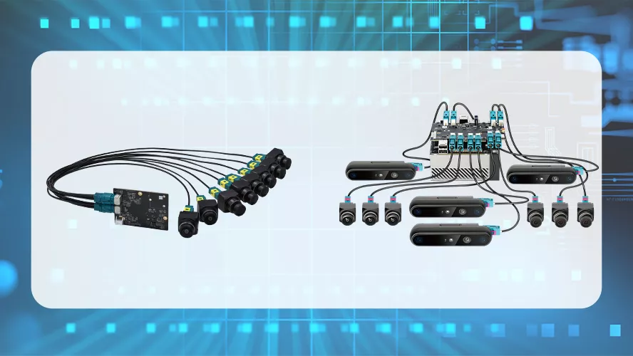
GMSL Camera Grabber Integration
SENSING GMSL camera grabber products provide a flexible solution for multi-camera applications with high-speed data capture capabilities.
Product Features
| Feature | Specification |
|---|---|
| Camera Input | 1-8 GMSL cameras |
| Interface | PCI-e Gen3.0 |
| Resolution | Up to 4K@30fps |
| OS Support | Linux (Ubuntu 18.04/20.04) |
Integration Process
1. Hardware Setup
- Install the grabber card in an available PCI-e slot
- Connect cameras to the designated ports
- Power on the system and verify hardware detection
2. Software Configuration
- Install driver packages from provided media or repository
- Configure camera parameters through the supplied SDK
- Test functionality through sample applications
Documentation & Resources
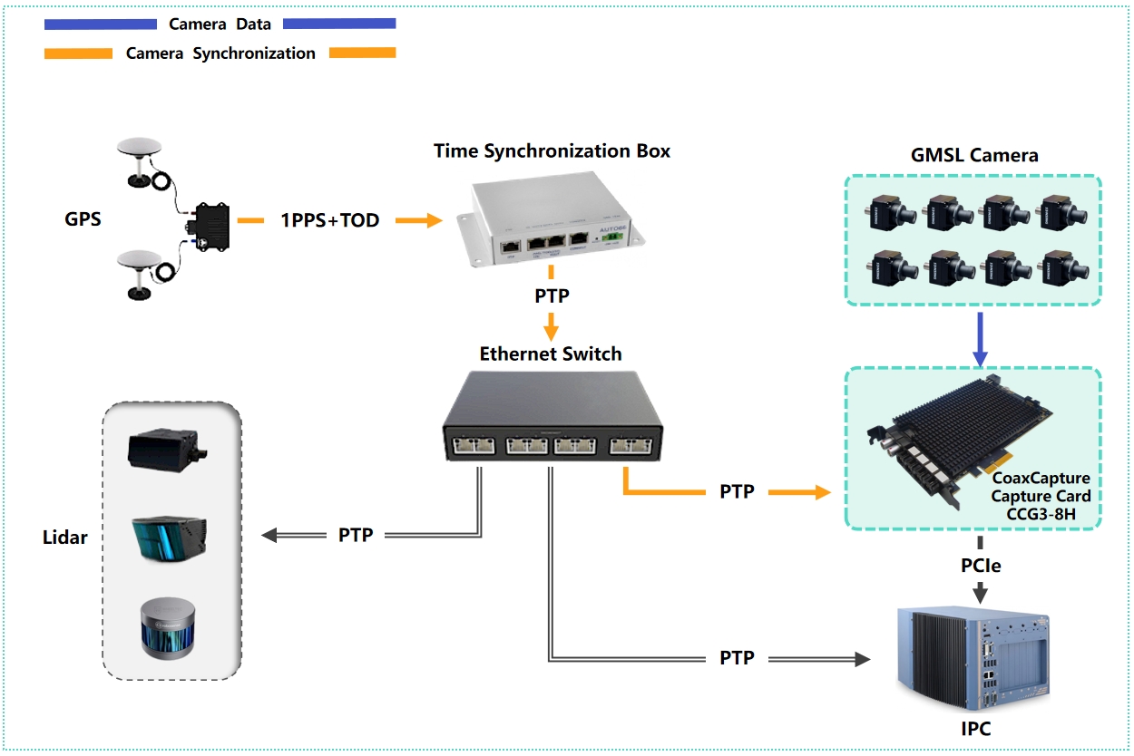
GMSL grabber solutions are optimized for multi-camera synchronization and high-throughput capture scenarios.
Third-party AI Box Integration
When integrating with third-party AI processing systems, compatibility verification and proper technical coordination are essential.
Integration Workflow
Review the AI Box manufacturer's "Compatible Camera List"
- Follow the manufacturer's standard integration procedure
- Refer to their documentation for configuration details
- Contact their technical support for assistance if needed
1. Establish Technical Collaboration
Create a joint communication channel between:
- AI Box manufacturer's technical team
- SENSING support team
- Customer implementation team
2. Technical Information Exchange
SENSING provides:
- Camera register configuration details
- I2C communication protocols
- Power requirements and sequence information
AI Box manufacturer implements:
- Driver adaptations
- Camera configuration profiles
- Integration testing procedures
The adaptation process typically requires 1-2 weeks depending on technical complexity.
Custom Platform Integration
For customers integrating SENSING cameras with custom deserializer implementations, detailed technical information and development support are provided.
System Architecture
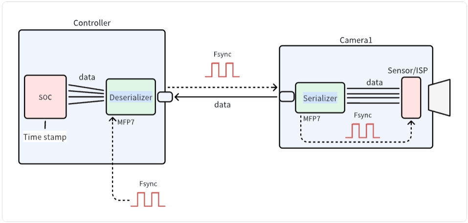
Technical Integration Process
1. Link Configuration
SENSING provides comprehensive technical documentation including:
- Camera register configuration
- Serializer/deserializer initialization sequences
- I2C communication protocol specifications
2. Software Development
/* MAX9296 I2C initialization example */
#define MAX9296_I2C_ADDR 0x90 // 8-bit address

int max9296_init() {
    // Initialize I2C bus
    i2c_init();

    // Disable MIPI output
    i2c_write(MAX9296_I2C_ADDR, 0x0313, 0x00);
    delay_ms(100);

    // Configure link settings for GMSL2 (6Gbps)
    i2c_write(MAX9296_I2C_ADDR, 0x0001, 0x02);

    // Configure link selection (default values)
    i2c_write(MAX9296_I2C_ADDR, 0x0006, 0xC0);

    // Configure MIPI rate (1200Mbps)
    i2c_write(MAX9296_I2C_ADDR, 0x0320, 0x2C);

    // Enable MIPI output
    i2c_write(MAX9296_I2C_ADDR, 0x0313, 0x02);

    return 0;
}
/* ISX031 sensor initialization example */
#define ISX031_I2C_ADDR 0x34 // 8-bit address
#define MAX9295_I2C_ADDR 0x80 // 8-bit address

int camera_init() {
    // Initialize deserializer first
    max9296_init();

    // Configure serializer (MAX9295A)
    i2c_write(MAX9295_I2C_ADDR, 0x02BE, 0x10); // MFP0 high
    i2c_write(MAX9295_I2C_ADDR, 0x0057, 0x12);
    i2c_write(MAX9295_I2C_ADDR, 0x005B, 0x11);

    // Configure data format (YUV422 8-bit)
    i2c_write(MAX9295_I2C_ADDR, 0x0318, 0x5E);

    // Camera power sequence
    i2c_write(MAX9295_I2C_ADDR, 0x02D3, 0x00); // MFP7 low
    delay_ms(300);
    i2c_write(MAX9295_I2C_ADDR, 0x02D3, 0x10); // MFP7 high

    return 0;
}
3. System Integration
BSP Integration
- Device tree configuration for CSI interfaces
- Kernel driver inclusion
- Media pipeline configuration
Application Development
/* Frame capture example */
int main() {
    // Open video device
    int fd = open("/dev/video0", O_RDWR);
    if (fd < 0) {
        perror("Failed to open camera device");
        return -1;
    }

    // Configure format
    struct v4l2_format fmt = {0};
    fmt.type = V4L2_BUF_TYPE_VIDEO_CAPTURE;
    fmt.fmt.pix.width = 1920;
    fmt.fmt.pix.height = 1536;
    fmt.fmt.pix.pixelformat = V4L2_PIX_FMT_YUYV;

    if (ioctl(fd, VIDIOC_S_FMT, &fmt) < 0) {
        perror("Failed to set format");
        close(fd);
        return -1;
    }

    // Buffer setup and capture operations
    // ...

    close(fd);
    return 0;
}
4. Technical Support Resources
Documentation
Complete register documentation, timing diagrams, and power sequence diagrams
Engineering Support
Technical consultation and debugging assistance for custom implementations
For custom integration projects, please contact SENSING technical support for detailed documentation and application-specific guidance.