Camera Triggering and Synchronization Guide
1. System Overview
The system consists of a Controller [including SoC and Deserializer], Cameras [including Serializer and Sensor], and other devices. SENSING's main product is the Camera.
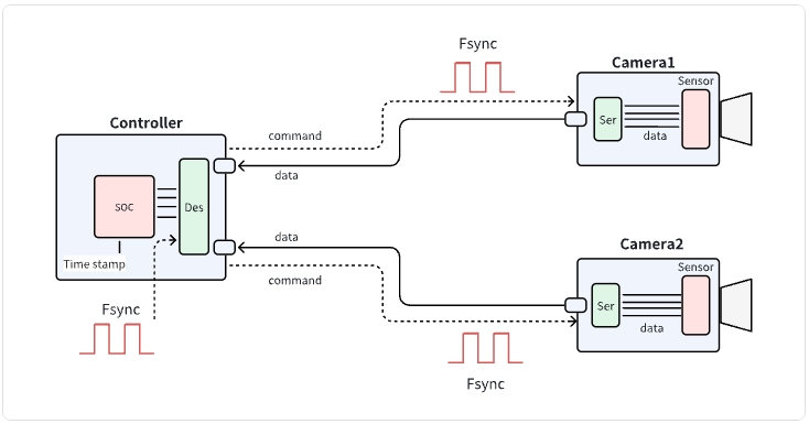
- An external Fsync signal is provided to the Controller. This signal is routed through the Controller's Deserializer and transparently forwarded to the Serializers of multiple cameras, enabling simultaneous hardware triggering.
- Both the Deserializer and Serializers must be properly configured to support Fsync signal passthrough.
- The same Fsync signal can also be distributed to LiDAR or other sensors, achieving multi-sensor hardware-level synchronization.
- As this is a hardware-based synchronization, the propagation delay of the Fsync signal and data transmission latency are negligible (typically in the microsecond range).
2. Verifying Synchronization
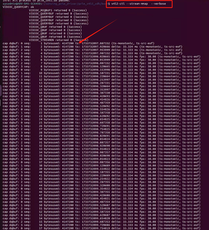
- The recommended method is to print and compare timestamps for each frame on the camera or controller side.
- If the timestamps from multiple cameras are closely aligned (or identical), synchronization is considered successful.
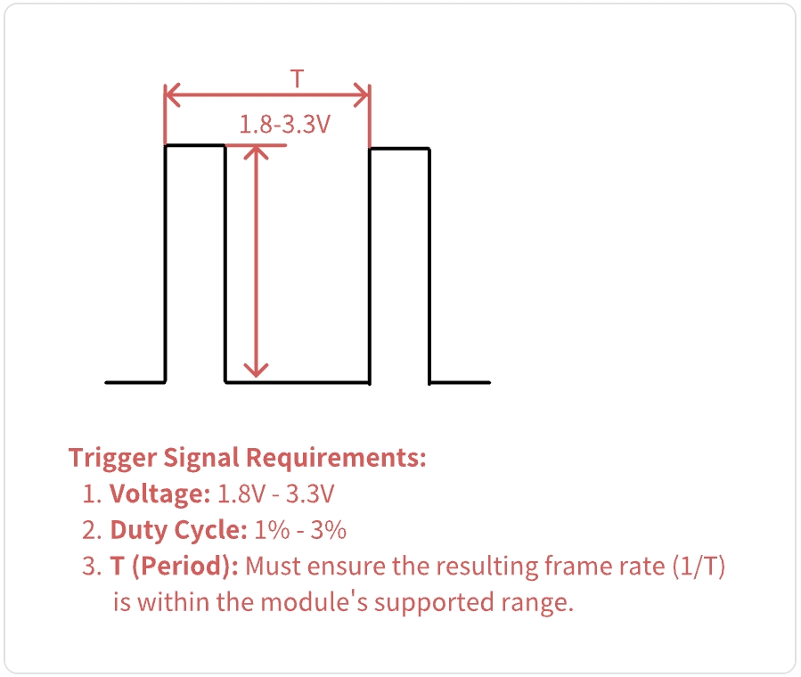
3. Fsync Signal Specifications
- The Fsync signal should meet specific requirements, including voltage level, pulse width, and frequency. Refer to your hardware documentation for detailed parameters.
4. Register Configuration Example
Below is a typical register configuration for enabling Fsync passthrough. Adjust addresses and values according to your hardware datasheet.
- The following configuration sets the MFP6 pin of MAX9296A as input and passes through the Fsync signal to the MFP7 and MFP8 pins of MAX9295A.
#!/bin/bash

#I2C总线号     16
#MAX9296A     I2CADDR= 0x48(7bit)
#MAX9295A     I2CADDR= 0x40(7bit)


#disable uart1(must)
i2ctransfer -y -f 16 w3@0x48 0x00 0x03 0x40

#MAX9296A MFP6 config, configure MFP6 pin of MAX9296A as input in passthrough mode
i2ctransfer -y -f 16 w3@0x48 0x02 0xC2 0x83
i2ctransfer -y -f 16 w3@0x48 0x02 0xC3 0xA7

sleep 0.2

#MAX9295A MFP7, MFP8 config, configure MFP7 and MFP8 pins of MAX9295A as output in passthrough mode
i2ctransfer -y -f 16 w3@0x40 0x02 0xD3 0x85
i2ctransfer -y -f 16 w3@0x40 0x02 0xD6 0x85
i2ctransfer -y -f 16 w3@0x40 0x00 0x10 0x21
sleep 0.3
#MAX9295A MFP7
i2ctransfer -y -f 16 w3@0x40 0x02 0xD3 0x84
i2ctransfer -y -f 16 w3@0x40 0x02 0xD5 0x07
#MAX9295A MFP8
i2ctransfer -y -f 16 w3@0x40 0x02 0xD6 0x84
i2ctransfer -y -f 16 w3@0x40 0x02 0xD8 0x07
Note: Always consult your device's datasheet for the correct register addresses and configuration values.
tip
For additional configuration options or specific requirements, please contact our technical support team for assistance.