TRD1 G2A
Overview
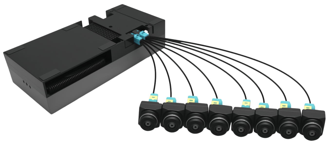
TRD1 G2A extends the official NVIDIA Jetson AGX THOR Developer Kit with GMSL connectivity, enabling rapid integration of GMSL camera streams on the THOR platform. Supports up to eight GMSL cameras.
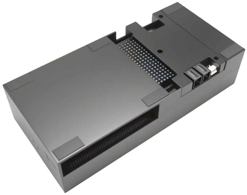
Key Features and Application
Features:
• Support NVIDIA JETSON THOR Platform
• Supported Camera Resolutions :Max 3840*2160
• Supported Camera Output Formats : RAW / YUV422
• Dimensions:L:243.12mm x W:112.4mm x H:56.88mm
• Compatible Camera Types :GMSL / GMSL2
• Maximum Supported Cameras :8 *GMSL
• SOC:NVIDlA Jetson T5000 Module
• Al Perfommance:2070 TFLOPS
• Memory:128 GB 256-bit LPDDR5X
Application:
• Robotics
• Industrial
• Medical
• Inspection
Getting Started
Hardware Overview
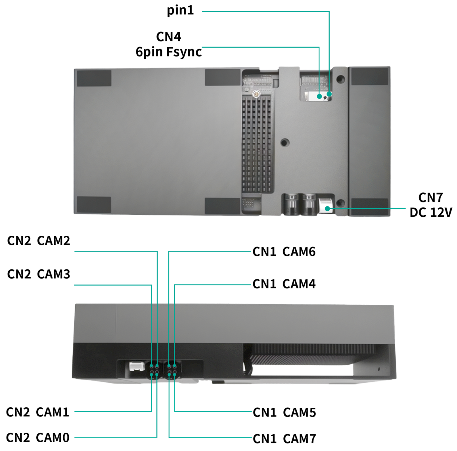
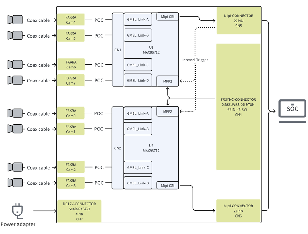
Block Diagram
Supported Camera List
You may choose the following camera combinations to connect to the TRD1 G2A.
| Camera Combination | Number of Supported Cameras | Jetpack 7.0 |
|---|---|---|
| Comb. 1 | 4*8MP/30FPS | - |
| Comb. 2 | 8*3MP/30FPS | - |
| Comb. 3 | 6*5MP/30FPS | - |
| Comb. 4 | 2 *8MP/30FPS+4 *3MP/30FPS | - |
| Comb. 5 | 3 *5MP/30FPS+4 *3MP/30FPS | - |
| Comb. 6 | 2 *8MP/30FPS+3 *5MP/30FPS | - |
NVIDIA JetPack (Jetpack 7.0 ) is the official software development kit (SDK) for the Jetson series of development boards. It includes the operating system, drivers, CUDA, cuDNN, TensorRT, and other development tools and libraries. Each JetPack version typically corresponds to a specific Jetson Linux version (formerly known as L4T - Linux for Tegra).
- 36.4.3: L4T R36.4.3 (Jetpack 6.2)
- 36.4: L4T R36.4 (Jetpack 6.1)
- 36.3: L4T R36.3 (Jetpack 6.0)
- 35.4.1: L4T R35.4.1 (Jetpack 5.1.2)
For more information, visit NVIDIA's official Jetson Download Center.
Hardware Preparation
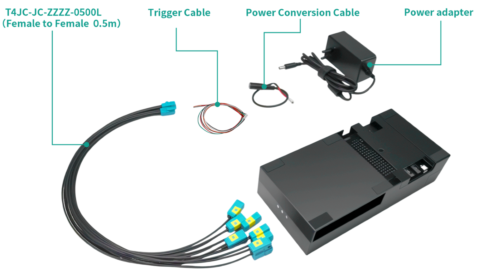
Parts List
| Serial number | Product model | Quantity | Remark |
|---|---|---|---|
| 1 | 945-14070-0080-000-MIPI | 1 | up to 8 cameras at most |
| 2 | T4JC-JC-ZZZZ-0500L (Female to Female 0.5m) | 2 | Standard configuration |
| 3 | Trigger Cable | 1 | Standard configuration |
| 4 | Power Conversion Cable | 1 | Standard configuration |
| 5 | Power adapter | 1 | Standard configuration |
| 6 | Multi-functional conversion socket | 1 | optional configuration |
Kit Contents
Installation Steps
- Connect the GMSL camera to the TRD1 G2A using the coaxial cable(up to 8 cameras at most)
- Connect the power supply(DC 9-16V)
- Power on the system(Jetson Thor)
Software Preparation
SDK Download
Select the appropriate driver package based on your camera type and JetPack version:
| Camera Type | JetPack Version | Download Link |
|---|---|---|
| GMSL2 Camera (YUV) | JP7.0 | Download |
Copy the full link address to DownGit to download
Quick Bring Up
We can use NVIDIA SDK Manager Linux Software or directly use the NVIDIA Linux Driver Package via Linux command line to flash JetPack OS into the NVIDIA Jetson device. For beginners, we highly recommend NVIDIA SDK Manager.
Jetpack version
- Jetpack 7.0
Supported SENSING Camera Modules
-
SG2-IMX390C-5200-G2A-Hxxx
- support max 8 cameras to bring up at the same time
-
SG2-AR0233-5200-G2A-Hxxx
- support max 8 cameras to bring up at the same time
-
SG3-ISX031C-GMSL2-Hxxx
- support max 8 cameras to bring up at the same time
-
SG3-ISX031C-GMSL2F-Hxxx
- support max 8 cameras to bring up at the same time
-
SG5-IMX490C-5300-GMSL2-Hxxx
- support max 6 cameras to bring up at the same time
-
SG8S-AR0820C-5300-G2A-Hxxx
- support max 4 cameras to bring up at the same time
-
SHF3L
- support max 8 cameras to bring up at the same time
-
SHF3H
- support max 4 cameras to bring up at the same time
Quick Bring Up
-
Copy the driver package to the working directory of the Jetson device, such as “/home/nvidia”
/home/nvidia/TRD1_G2A_YUV_JP7.0_L4TR38.2 -
Enter the driver directory,
cd TRD1_G2A_YUV_JP7.0_L4TR38.2
chmod a+x ./install.sh
./install.sh -
Use the "sudo /opt/nvidia/jetson-io/jetson-io.py" command to select the corresponding device
sudo /opt/nvidia/jetson-io/jetson-io.py

1.select "Configure Jetson AGX CSI Connector"
2.select "Configure for compatible hardware"
3.select "Jetson Sensing SG8A_AGTH_G2Y_A1 YUV GMSL2x8"
4.select "Save pin changes"
5.select "Save and reboot to reconfigure pins" -
If step 3 cannot be executed, you can manually modify the extlinux.conf file to apply the device tree.
sudo vi /boot/extlinux/extlinux.conf -
Modify the file to the following content, then reboot.
TIMEOUT 30
DEFAULT JetsonIO

MENU TITLE L4T boot options

LABEL primary
      MENU LABEL primary kernel
      LINUX /boot/Image
      INITRD /boot/initrd
      APPEND ${cbootargs} root=PARTUUID=d2f22c03-8ac9-473f-ba9a-8c8cea392567 rw rootwait rootfstype=ext4 mminit_loglevel=4 earlycon=tegra_utc,mmio32,0xc5a0000 console=ttyUTC0,115200 clk_ignore_unused firmware_class.path=/etc/firmware fbcon=map:0 efi=runtime

# When testing a custom kernel, it is recommended that you create a backup of
# the original kernel and add a new entry to this file so that the device can
# fallback to the original kernel. To do this:
#
# 1, Make a backup of the original kernel
#      sudo cp /boot/Image /boot/Image.backup
#
# 2, Copy your custom kernel into /boot/Image
#
# 3, Uncomment below menu setting lines for the original kernel
#
# 4, Reboot

# LABEL backup
#    MENU LABEL backup kernel
#    LINUX /boot/Image.backup
#    INITRD /boot/initrd
#    APPEND ${cbootargs}

LABEL JetsonIO
        MENU LABEL Custom Header Config: <CSI Jetson Sensing SG8A_AGTH_G2Y_A1 YUV GMSL2x4>
        LINUX /boot/Image
        FDT /boot/dtb/kernel_tegra264-p4071-0000+p3834-0008-nv.dtb
        INITRD /boot/initrd
        APPEND ${cbootargs} root=PARTUUID=d2f22c03-8ac9-473f-ba9a-8c8cea392567 rw rootwait rootfstype=ext4 mminit_loglevel=4 earlycon=tegra_utc,mmio32,0xc5a0000 console=ttyUTC0,115200 clk_ignore_unused firmware_class.path=/etc/firmware fbcon=map:0 efi=runtime
OVERLAYS /boot/tegra264-camera-yuv-gmsl2x8-overlay.dtbo -
Bring up the camera
cd TRD1_G2A_AGX_THOR_YUV_JP7.0_L4TR38.2
chmod +x quick_bring_up.sh
./quick_bring_up.sh
Select the corresponding camera model and port to bring up the camera.
The following example demonstrates how to initialize the SG8S-AR0820C-5300-G2A-Hxxx camera.
This package is use for AGX Thor & Jetson_Linux_R38.2.0
Select the camera type:
0:SG2-IMX390C-5200-G2A-Hxxx
1:SG2-AR0233C-5200-G2A-Hxxx
2:SG3S-ISX031C-GMSL2-Hxxx
3:SG3S-ISX031C-GMSL2F-Hxxx
4:SG5-IMX490C-5300-GMSL2-Hxxx
5:SG8S-AR0820C-5300-G2A-Hxxx
6:SHF3L
7:SHW3H
4
Select the camera port to light up[0-7]:
0
ready bring up camera
Setting pipeline to PAUSED ...
Pipeline is live and does not need PREROLL ...
Pipeline is PREROLLED ...
Setting pipeline to PLAYING ...
New clock: GstSystemClock
WARNING: from element /GstPipeline:pipeline0/GstV4l2Src:v4l2src0: Signal lost
Additional debug info:
../sys/v4l2/gstv4l2src.c(556): gst_v4l2src_query_preferred_size (): /GstPipeline:pipeline0/GstV4l2Src:v4l2src0:
No input source was detected - video frames invalid
/GstPipeline:pipeline0/GstV4l2Src:v4l2src0.GstPad:src: caps = video/x-raw, format=(string)UYVY, width=(int)3840, height=(int)2160, framerate=(fraction)30/1, interlace-mode=(string)progressive, colorimetry=(string)2:4:7:1
/GstPipeline:pipeline0/GstXvImageSink:xvimagesink0.GstPad:sink: caps = video/x-raw, format=(string)UYVY, width=(int)3840, height=(int)2160, framerate=(fraction)30/1, interlace-mode=(string)progressive, colorimetry=(string)2:4:7:1
Redistribute latency...
0:02:22.0 / 99:99:99. -
Mixed use of 3G mode cameras (with F identifier: XXX-GMSL2F-XXX) and 6G mode cameras (without F identifier)
If you wish to use the mixed mode, we have provided the following methods in the driver for your use.
a.Determine the corresponding mode for each camera channel, where 3G is represented by (1) and 6G by (0).
b.Load the driver manually according to the actual situation.
sudo insmod ./ko/max96712.ko
sudo insmod ./ko/sgx-yuv-gmsl2.ko enable_3G_0=1,1,0,0 enable_3G_1=0,0,1,1
enable_3G_0 represents the first input channel. The value
1,1,0,0indicates that the first and second cameras operate in 3G mode, while the third and fourth cameras operate in 6G mode.enable_3G_1 represents the second input channel. The value
0,0,1,1indicates that the first and second cameras operate in 6G mode, while the third and fourth cameras operate in 3G mode. -
Camera Trigger Sync
Modify quick_bring_up.sh script and re-run it.
v4l2-ctl -d /dev/video0 -c trig_pin=0x00020007,trig_mode=2
v4l2-ctl -d /dev/video1 -c trig_pin=0x00020007,trig_mode=2
v4l2-ctl -d /dev/video2 -c trig_pin=0x00020007,trig_mode=2
v4l2-ctl -d /dev/video3 -c trig_pin=0x00020007,trig_mode=2
v4l2-ctl -d /dev/video4 -c trig_pin=0x00020007,trig_mode=2
v4l2-ctl -d /dev/video5 -c trig_pin=0x00020007,trig_mode=2
v4l2-ctl -d /dev/video6 -c trig_pin=0x00020007,trig_mode=2
v4l2-ctl -d /dev/video7 -c trig_pin=0x00020007,trig_mode=2
8.1 External Trigger Mode
For Adapter Board CN4, the PIN1(CAM-FSYNC1) and PIN6 correspond to the external trigger signal pin and ground pin respectively. Connect the corresponding pins of the signal generator to these pins.
8.2 Internal Trigger Mode
a.load the driver
sudo insmod ko/pwm-gpio.ko

b.Export PWM channel 0 (pwmchip4 is a newly generated node after loading the driver)
echo 0 > /sys/class/pwm/pwmchip4/export

c.Set the period to 33333333 (corresponding to 30 Hz)
echo 33333333 > /sys/class/pwm/pwmchip4/pwm0/period

d.Set the duty cycle
echo 10000000 > /sys/class/pwm/pwmchip4/pwm0/duty_cycle

e.Enable PWM output
echo 1 > /sys/class/pwm/pwmchip4/pwm0/enable
Integration with SENSING Driver Source Code
- Compile Image & dtb Refer to the following command to integrate Dtb and Kernel source code to your kernel
cp camera-driver-package/source/hardware Linux_for_Tegra/source/hardware -r
cp camera-driver-package/source/kernel Linux_for_Tegra/source/kernel -r
cp camera-driver-package/source/nvidia-oot Linux_for_Tegra/source/nvidia-oot -r
- Go to the root directory of your source code and recompile
cd <install-path>/Linux_for_Tegra/source
export CROSS_COMPILE_AARCH64=toolchain-path/bin/aarch64-buildroot-linux-gnu-
export KERNEL_HEADERS=$PWD/kernel/kernel-noble
export INSTALL_MOD_PATH=<install-path>/Linux_for_Tegra/rootfs/
make -C kernel
make modules
make dtbs
sudo -E make install -C kernel

cp kernel/kernel-noble/arch/arm64/boot/Image <install-path>/Linux_for_Tegra/kernel/Image
cp nvidia-oot/device-tree/platform/generic-dts/dtbs/* <install-path>/Linux_for_Tegra/kernel/dtb/
- Install the newly generated Image and dtb to your nvidia device and reboot to let them take effect
dtb:nvidia-oot/device-tree/platform/generic-dts/dtbs/
Image: kernel/kernel-noble/arch/arm64/boot/

tegra-camera.ko:nvidia-oot/drivers/media/platform/tegra/camera/
nvhost-nvcsi.ko:nvidia-oot/drivers/video/tegra/host/nvcsi/
- Copy the image,dtb,ko generated by the above compilation to the corresponding location of jetson
sudo cp *.dtbo /boot/
sudo cp Image /boot/Image
sudo cp tegra-camera.ko /lib/modules/6.8.12-tegra/updates/drivers/media/platform/tegra/camera/
sudo cp nvhost-nvcsi.ko /lib/modules/6.8.12-tegra/updates/drivers/video/tegra/host/nvcsi/
- Select the device tree you installed
sudo /opt/nvidia/jetson-io/jetson-io.py

1.select "Configure Jetson AGX CSI Connector"
2.select "Configure for compatible hardware"
3.select "Jetson Sensing SG8A_AGTH_G2Y_A1 YUV GMSL2x8"
4.select "Save pin changes"
5.select "Save and reboot to reconfigure pins"
- Install camera driver
sudo insmod ./ko/max96712.ko
sudo insmod ./ko/sgx-yuv-gmsl2.ko
-
Bring up the camera
CAM0
v4l2-ctl -d /dev/video0 -c sensor_mode=?,trig_pin=? gst-launch-1.0 v4l2src device=/dev/video0 ! xvimagesink -ev
CAM1
v4l2-ctl -d /dev/video1 -c sensor_mode=?,trig_pin=? gst-launch-1.0 v4l2src device=/dev/video1 ! xvimagesink -ev
CAM2
v4l2-ctl -d /dev/video2 -c sensor_mode=?,trig_pin=? gst-launch-1.0 v4l2src device=/dev/video2 ! xvimagesink -ev
CAM3
v4l2-ctl -d /dev/video3 -c sensor_mode=?,trig_pin=? gst-launch-1.0 v4l2src device=/dev/video3 ! xvimagesink -ev
CAM4
v4l2-ctl -d /dev/video4 -c sensor_mode=?,trig_pin=? gst-launch-1.0 v4l2src device=/dev/video4 ! xvimagesink -ev
CAM5
v4l2-ctl -d /dev/video0 -c sensor_mode=?,trig_pin=? gst-launch-1.0 v4l2src device=/dev/video5 ! xvimagesink -ev
CAM6
v4l2-ctl -d /dev/video0 -c sensor_mode=?,trig_pin=? gst-launch-1.0 v4l2src device=/dev/video6 ! xvimagesink -ev
CAM7
v4l2-ctl -d /dev/video0 -c sensor_mode=?,trig_pin=? gst-launch-1.0 v4l2src device=/dev/video7 ! xvimagesink -ev