SG3-IMX900C-MIPI Camera
SG3-IMX900C-MIPI has been discontinued and is no longer available for purchase. Its product page has been taken down from the SENSING website, so purchase links are no longer provided here.
This documentation stays online as technical reference for existing deployments. For new designs or replacement recommendations, please contact SENSING technical support.
Overview
The SG3-IMX900C-MIPI camera features the SONY IMX900 CMOS image sensor with 3.2MP resolution. This high-performance camera delivers 2064×1552 resolution at up to 30fps with HDR support. Pre-focused with an M12 lens and compatible with various SoC platforms, it's ideal for advanced imaging applications.
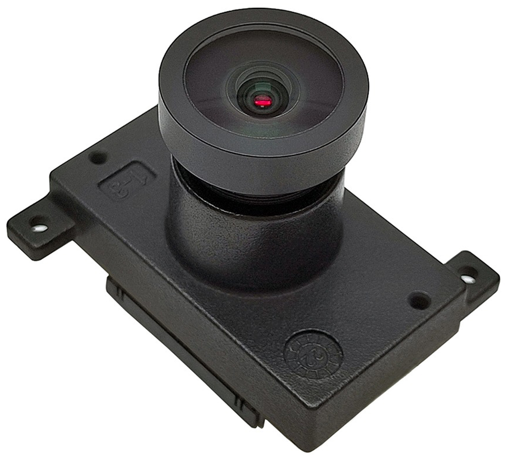
Technical Specifications
Key Features
| Parameter | Value |
|---|---|
| Sensor | SONY 3.2MP IMX900 RGGB |
| ISP | / |
| Image Size | 1/3.1 inch CMOS |
| Exposure mode | Global shutter |
| Output Pixels | 2064H×1552V |
| Frame rate | 30fps |
| Pixel Size | 2.25μm×2.25μm |
| HDR Support | Yes |
| Output data | MIPI/RAW12 |
| Power Supply | 3.3V |
| Current | < 350mA @3.3VDC |
| Camera interface | FPC |
| Connector | FH67-30S-0.5SV |
| Operating temp. | -30 to +75°C |
| Performance temp. | -10 to +60°C |
| Storage temp. | -40 to +85°C |
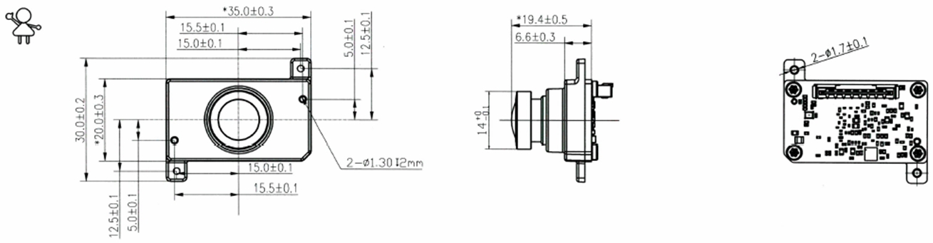
| Dimensions | W: 30mm, L:35mm, H:19.4mm |
| Weight | < 50g |
Physical Dimensions
Lens Options
Hardware Integration
System Architecture

I2C Address Configuration
| Component | I2C Address |
|---|---|
| EEPROM | 0xA0 (8-bit address) |
| Sensor | 0x6C (8-bit address) |
Connector Pin Definitions
| NO | Pin Name | Type | Description |
|---|---|---|---|
| 1 | FRSYNC1 | INPUT:1.8V | Frame sync signal 1 |
| 2 | FRSYNC2 | INPUT:1.8V | Frame sync signal 2 |
| 3 | GPIO0 | OUTPUT: | GPIO signal |
| 4 | GND | POWER | Ground |
| 5 | XHS | I/O:1.8V | Horizontal sync signal in master mode |
| 6 | XVS | I/O:1.8V | Vertical sync signal in master mode |
| 7 | GND | POWER | Ground |
| 8 | D0_N | OUTPUT | MIPI |
| 9 | D0_P | OUTPUT | MIPI |
| 10 | GND | POWER | Ground |
| 11 | D1_N | OUTPUT | MIPI |
| 12 | D1_P | OUTPUT | MIPI |
| 13 | GND | POWER | Ground |
| 14 | CLK_N | OUTPUT | MIPI |
| 15 | CLK_P | OUTPUT | MIPI |
| 16 | GND | POWER | Ground |
| 17 | D2_N | OUTPUT | MIPI |
| 18 | D2_P | OUTPUT | MIPI |
| 19 | GND | POWER | Ground |
| 20 | D3_N | OUTPUT | MIPI |
| 21 | D3_P | OUTPUT | MIPI |
| 22 | GND | POWER | Ground |
| 23 | POW_RES | INPUT:3.3V/1.8V | Power-on reset signal |
| 24 | SENSOR-CLK | INPUT:54MHZ(1.8V) | Clock signal input (module has internal oscillator) |
| 25 | GND | POWER | Ground |
| 26 | CAM-SCL | I/O:3.3V | UP 1K(FRSYNC:I2C Address 7' 36) |
| 27 | CAM-SDA | I/O:3.3V | UP 1K(FRSYNC:I2C Address 7' 36) |
| 28 | GND | POWER | Ground |
| 29 | VCC-3.3V | POWER | 3.3V Power Supply |
| 30 | VCC-3.3V | POWER | 3.3V Power Supply |
Frame Sync (Fsync)
The SG3-IMX900C-MIPI supports external frame synchronization. The host drives the sync pins on the FPC connector directly; the signal requirements are listed below.
Sync Signal Requirements
| # | Signal | Connector Pin | PWM Trigger Requirement | Description |
|---|---|---|---|---|
| 1 | XVS | Pin 6 (I/O, 1.8V) | Frequency: 30 Hz, Duty cycle: 10% | Vertical (frame) sync. The XVS period determines the frame period; 30 Hz corresponds to the 30 fps maximum frame rate of this module. |
| 2 | XHS | Pin 5 (I/O, 1.8V) | Frequency: 83 kHz, Duty cycle: >= 90% | Horizontal (line) sync. |
For synchronized triggering (slave mode), XVS and XHS must be supplied at the same time and both must meet the requirements above. Supplying only one of them will not give a synchronized frame output.
Master and Slave Mode
| Mode | XVS / XHS direction | Typical use |
|---|---|---|
| Master | Output from the camera module | Single camera, or the module acts as the sync source of the system |
| Slave | Input to the camera module | Multi-camera synchronized capture, or synchronization with an external trigger source |
As listed in the connector pin definitions above, XHS (Pin 5) and XVS (Pin 6) are the sync signals the module outputs in master mode; in slave mode the same pins are driven by the host SoC.
Multi-Camera Synchronization
- Generate one pair of XVS / XHS signals on the host side and fan them out to every camera, so that all modules share the same trigger edge.
- Keep the sync signals at 1.8V logic level to match the pin definitions. Add level shifting if the host GPIO is 3.3V.
- Keep the sync signal trace and cable lengths as close as possible between cameras to minimize skew.
- Set every camera that takes part in the synchronization to slave mode, and keep only one sync source in the system.
Pin 1 (FRSYNC1) and Pin 2 (FRSYNC2) are the 1.8V frame sync inputs of the module. If your design drives these pins instead of XVS / XHS, please confirm the wiring with SENSING technical support before finalizing the board layout.
Power-Up Sequence

The SG3-IMX900C-MIPI camera has minimal power-up sequence requirements. Simply ensure that the RESET signal is asserted after power supplies are stable.
Installation Guide
Quick Setup
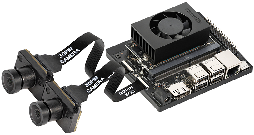
- Connect the FPC cable to the camera module
- Mount the camera onto the Jetson Orin Nano/NX Developer Kit
- Power on the system and configure software drivers
Software & Driver Support
The driver package for the SG3-IMX900C-MIPI camera is currently under development and will be released soon. Please stay tuned for updates.
Accessories
FPC Cable Options
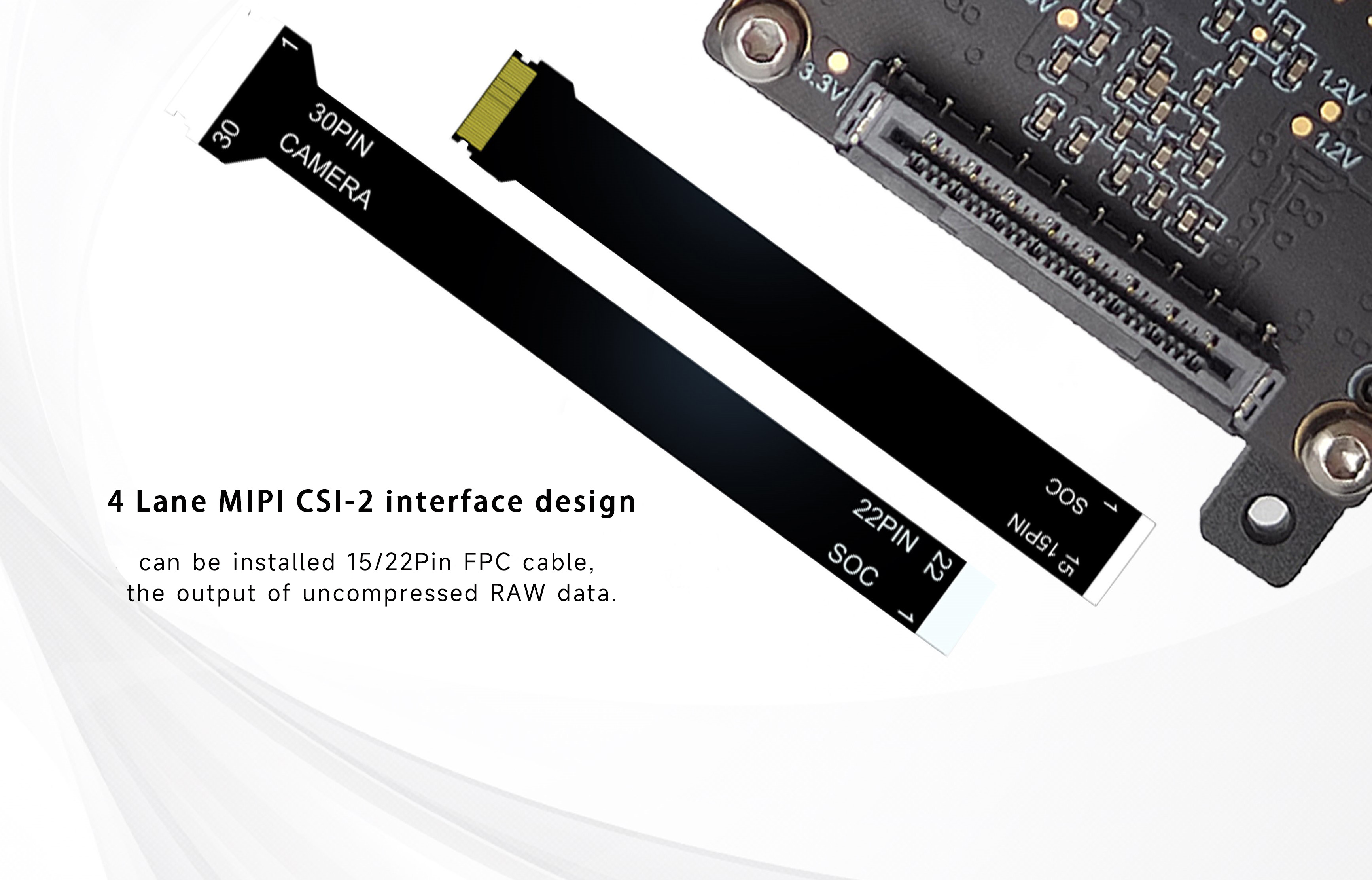
The SG3-IMX900C-MIPI supports two FPC cable types for different connection requirements:
| Cable Type | Part Number | Specification |
|---|---|---|
| 22-Pin FPC | 339901-0010 | 0.5mm Pitch |
| 15-Pin FPC | 339901-0011 | 1.0mm Pitch |