Camera Intrinsic Parameters
This document provides comprehensive information about camera intrinsic parameters, including how to obtain them, their formats, and applications.
Q1: Availability and Identification
Intrinsic Parameter Availability
Starting from 2023, all SENSING cameras come with pre-calibrated intrinsic parameters stored in the camera. For cameras produced before 2023, intrinsic parameters were only calibrated upon specific customer request.
Identifying Camera Manufacturing Year
You can identify the manufacturing year of the camera through the SN code:
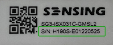
The image below shows a camera with:
- SN Code: H190S-E01220525
- Product Model: SG3-ISX031C-GMSL2-H190S
| Prefix | Manufacturing Year | Intrinsic Parameters Status |
|---|---|---|
| Dxxxxxx | 2021 | Not calibrated by default |
| Exxxxxx | 2022 | Not calibrated by default |
| Fxxxxxx | 2023 | Calibrated by default |
| Gxxxxxx | 2024 | Calibrated by default |
| Hxxxxxx | 2025 | Calibrated by default |
Q2: Accessing Camera Intrinsic Parameters
Method 1: Following Model-Specific Instructions
Below are examples of models and their corresponding instruction documents for obtaining intrinsic parameters:
| # | Model Examples | Instruction Document | Notes |
|---|---|---|---|
| 1 | SG2-AR0233C-5200-G2A-Hxxx SG2-IMX390C-5200-GMSL2-Hxxx SG5-IMX490C-5300-GMSL2-Hxxx SG8-AR0820C-5300-GMSL2-Hxxx SG8-OX08BC-5300-GMSL2-Hxxx | Intrinsic Parameter Reading Instructions for GW5200 & GW5300 ISP Models | Models with 5200 or 5300 in the model name |
| 2 | SG2-AR0231C-0202-GMSL-Hxxx | Intrinsic Parameter Reading Instructions for AP0101 & AP0202 ISP Models | Models with 0101 or 0202 in the model name |
| 3 | SG3S-ISX031-GMSL2F-Hxxx | ISX031(IMX623) GMSL2 Module Intrinsic Parameter Reading Instructions | Models with ISX031 or IMX623 in the model name |
| 4 | SG2-AR0233C-GMSL2 (raw camera) SG8-IMX728C-G2G-Hxxx (raw) SG3S-OX03JC-G2F-Hxxx S56x binocular | Intrinsic Parameter Reading Instructions for GMSL2 and FPDLINK III Series Modules without ISP | Models with GMSL2 or FPDLINK in the name but without an ISP model number |
| 5 | SG1-OX01FC-GMSL-Hxxx | Intrinsic Parameter Reading Instructions for OX01F10 SENSOR Models | Models with OX01FC in the model name |
Data Format References
- For standard cameras: Refer to Camera OTP Data Format Definition_pub (Password: SensingOTP2024)
- For binocular cameras: Refer to Depth Camera OTP Data Format Definition_pub (Password: SensingOTP2024)
Method 2: Using SensingTech Online Service Platform
You can download intrinsic parameters individually through the SensingTech Customer Self-service Information Query Platform. Note that the SN code of the camera is required.
Q3: Camera Model Types
Two types of camera models are used for intrinsic parameters:
- Pinhole Model: Used for lenses with fields of view up to 120 degrees (including H120)
- Fisheye Model: Used for lenses with fields of view up to 190 degrees
Pinhole Camera Model
The pinhole camera model with distortion correction can be represented by:
[x']   [x(1 + k₁r² + k₂r⁴ + k₃r⁶)/(1 + k₄r² + k₅r⁴ + k₆r⁶) + 2p₁xy + p₂(r² + 2x²)]
[y'] = [y(1 + k₁r² + k₂r⁴ + k₃r⁶)/(1 + k₄r² + k₅r⁴ + k₆r⁶) + p₁(r² + 2y²) + 2p₂xy]
Where:
- (x, y) are the normalized image coordinates
- (x', y') are the distorted image coordinates
- r² = x² + y² is the squared radius
- k₁, k₂, k₃, k₄, k₅, k₆ are the radial distortion coefficients
- p₁, p₂ are the tangential distortion coefficients
By default, parameters K1-K6 are used for distortion correction.
Fisheye Camera Model
The fisheye camera model can be represented by:
r(θ) = k₁θ + k₂θ³ + k₃θ⁵ + k₄θ⁷
Where:
- θ is the angle between the incoming light ray and the optical axis
- r is the distance from the optical center on the image plane
- k₁, k₂, k₃, k₄ are the fisheye distortion coefficients
This model is specifically designed for wide-angle lenses with fields of view exceeding 120 degrees.
Q4: Reading Intrinsic Parameters on Third-Party Platforms
If your camera has calibrated intrinsic parameters, you can access them through the following methods:
Using I2C Tools
You can use the platform's I2C tools to read intrinsic parameters according to the provided instructions.
I2C Reading Process:
- Identify the correct I2C bus and device address for your camera (typically 0x51 for EEPROM)
- Use I2C commands to read specific register addresses containing intrinsic parameters
- For Linux systems:
- Use
i2cdetect -r -y <bus_number>to scan for available devices - Use
i2ctransfer -y -f <bus_number> w2@<device_address> <reg_high> <reg_low> r<count>to read data
- Use
Important Note: When multiple modules are connected to a domain controller simultaneously, the default I2C addresses must be remapped to unique addresses to ensure reading from the correct module.
Using Platform-Provided Interfaces
Some platforms may have already implemented interfaces based on our documentation. Please consult with your platform provider for specific usage methods.
Q5: Parameter Conversion and Usage
Converting Intrinsic Parameters
Example of Intrinsic Parameter Storage:
The following table shows an example of how the focal length parameter (fx) is stored in registers:
| Register | Value | Description | Type and Unit | Flag |
|---|---|---|---|---|
| 0x0065 | 0x59 | |||
| 0x0066 | 0xAD | |||
| 0x0067 | 0xFE | |||
| 0x0068 | 0xD6 | 1426.1570701402 | value:fx type: double unit: pixels | YES_CRC32_4 |
| 0x0069 | 0xA0 | |||
| 0x006A | 0x48 | |||
| 0x006B | 0x96 | |||
| 0x006C | 0x40 |
These register values can be converted to the actual focal length parameter (fx = 1426.1570701402 pixels) using the string conversion formula described below.
String Conversion Formula:
#include "stdio.h"

int main(void)
{
    unsigned char pMem[] = {0x59, 0xad, 0xfe, 0xd6, 0xa0, 0x48, 0x96, 0x40};
    double *p = (double*)pMem;
    printf("%.10f\r\n", *p);

    return 0;
}
Converting Floating Point Values
For focal length conversion:
| Address | Parameter | Hex Value | Decoded Value / Description | Status |
|---|---|---|---|---|
0x0021 | 0xEC | YES_CRC32_4 | ||
0x0022 | Focal Length | 0x51 | 4.26 Focal Length | YES_CRC32_4 |
0x0023 | 0x88 | YES_CRC32_4 | ||
0x0024 | 0x40 | YES_CRC32_4 |
Use the following code for conversion:
unsigned char ppm[] = { 0xEC, 0x51, 0x88, 0x40 };
float* m = (float*)ppm;
printf("%f\r\n", *m);
Reading and Converting SN Codes
The SN code is stored as part of the OTP data in the module, following the same format as intrinsic parameters.
SN Code Conversion Process:
- Read the hexadecimal values from the SN code registers (addresses 0x0120-0x0133)
- Convert each hexadecimal value to its ASCII character representation
- Combine the characters to form the complete SN code
- Stop at the first 0xFF value, which indicates the end of the SN string
SN Code Conversion Example:
| Register | Address | Value | Ref No. | Notes |
|---|---|---|---|---|
| SN | 0x0120 | 0x48 | H60S-D11200036 | Model code contains 32 bytes; unused positions are filled with 0xFF |
| 0x0121 | 0x36 | |||
| 0x0122 | 0x30 | |||
| 0x0123 | 0x53 | |||
| 0x0124 | 0x2D | |||
| 0x0125 | 0x44 | |||
| 0x0126 | 0x31 | |||
| 0x0127 | 0x31 | |||
| 0x0128 | 0x32 | |||
| 0x0129 | 0x30 | |||
| 0x012A | 0x30 | |||
| 0x012B | 0x30 | |||
| 0x012C | 0x33 | |||
| 0x012D | 0x36 | |||
| 0x012E | 0xFF | |||
| 0x012F | 0xFF | |||
| 0x0130 | 0xFF | |||
| 0x0131 | 0xFF | |||
| 0x0132 | 0xFF | |||
| 0x0133 | 0xFF | |||
| 0x0134 | 0xFF | |||
| 0x0135 | 0xFF | |||
| 0x0136 | 0xFF | |||
| 0x0137 | 0xFF | |||
| 0x0138 | 0xFF | |||
| 0x0139 | 0xFF | |||
| 0x013A | 0xFF | |||
| 0x013B | 0xFF | |||
| 0x013C | 0xFF | |||
| 0x013D | 0xFF | |||
| 0x013E | 0xFF | |||
| 0x013F | 0xFF | |||
| 0x0140 | 0xFF |
SN String Conversion Code:
#include <stdio.h>

int main() {
    unsigned char pMem[] = {0x48, 0x36, 0x30, 0x53, 0x2d, 0x44, 0x31, 0x31, 0x32, 0x30, 0x30, 0x33, 0x36};

    int arrayLength = sizeof(pMem) / sizeof(pMem[0]);

    char result[arrayLength + 1];

    for (int i = 0; i < arrayLength; i++) {
        result[i] = pMem[i];
    }
    result[arrayLength] = '\0';

    printf("SN: %s\n", result);

    return 0;
}
Using Intrinsic Parameters
Intrinsic parameters can be used with OpenCV. Implementation code must be developed by the customer.
Reference article: OpenCV Camera Intrinsic Calibration and Usage"
Q6: Working with Multiple Cameras
Reading Parameters from Multiple Cameras
For Camera with GW5200/GW5300 ISP
-
For a single camera connection:
- In a Linux environment, scan the EEPROM I2C address (0x51) using
i2cdetect -r -y - Read the register values using:
sudo i2ctransfer -y -f 1 w2@0x51 0x00 0x01 r1
- In a Linux environment, scan the EEPROM I2C address (0x51) using
-
For multiple cameras of the same model:
- Remap the EEPROM address 0x51 (0xA2) to different addresses by modifying registers 0x42 and 0x43 of 9295/96717F
- Write the original address 0x51 (0xA2) to register 0x43
- Write the destination addresses (e.g., 0x54/0xA8, 0x55/0xAA) to register 0x42 as defined in the device tree file
Address Remapping Process:
- Original Setup: All cameras initially have the same I2C address (0x51)
- Configuration: Write to registers 0x42 and 0x43 of MAX9295/MAX96717F
- Result: Each camera now has a unique address (e.g., 0x54, 0x55, etc.)
- Reading: Use the new unique addresses to read data from each camera individually
For Camera with ISX031 sensor
Follow the same method as above:
- Write the original address 0x34 (0x1A) to register 0x43
- Write destination addresses (e.g., 0x54/0xA8, 0x55/0xAA) to register 0x42 as defined in the device tree file
Q7: Technical Specifications
Parameter Storage Addresses
Pinhole and fisheye model parameters are stored at different addresses:
- Pinhole mode: Addresses 0x85-0xC4 store K1, K2, P1, P2, K3, K4, K5, K6 parameters (FOV < 120°)
- Fisheye mode: Addresses 0xC5-0xE4 store K1, K2, K3, K4 parameters (FOV > 120°)
Storage Addresses Table:
| Parameter Type | Model Type | Address Range | Parameters |
|---|---|---|---|
| Intrinsic Matrix | Both | 0x45-0x54 | Fx, Fy, Cx, Cy |
| Distortion | Pinhole | 0x85-0xC4 | K1, K2, P1, P2, K3, K4, K5, K6 |
| Distortion | Fisheye | 0xC5-0xE4 | K1, K2, K3, K4 |
| SN Code | Both | 0x0120-0x0133 | ASCII characters |
Calibration Precision
- RMS Differences: RMS calculation formulas may vary between different batches of cameras
- Calibration Error Range:
- COD precision error: AA lenses have standards, threaded lenses do not
- Equivalent focal length error: Controlled according to lens design tolerance
- Reprojection error (RMS): Average reprojection error is 0.25
Calibration Standards and Accuracy Assessment
The evaluation standards include:
- Reprojection error
- Stability of intrinsic parameters and distortion parameters
- Calibration accuracy at different viewing angles
- Distortion correction effects
- Testing in actual applications