Getting Started with GMSL2 Camera Repeater
Overview
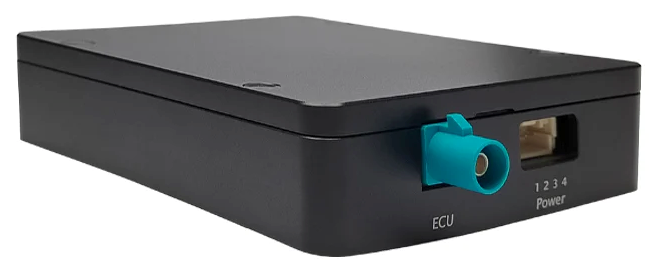
The GMSL2 Repeater is designed by SZ SENSING TECH CO.,LTD., which can realize one GMSL2 input and one GMSL2 output, so as to extend the transmission distance.
Key Features
- Lossless data transmission
- Full GMSL/GMSL2 compatibility
- Ultra-low latency (microsecond level)
- Minimal insertion loss
Specifications
| Parameter | Value |
|---|---|
| Transport Protocol | GMSL / GMSL2 |
| Input Ports | 1 |
| Output Ports | 1 |
| Input Interface | 1× GMSL2 |
| Output Interface | 1× GMSL2 |
| Supported Data Rates | 1.5Gbps, 3Gbps, 6Gbps |
| Maximum Resolution | Up to 3840×2160 |
| Output Synchronization Accuracy | < 10μs |
| Power Supply | Yes |
| Connector | Fakra Z Type |
| Operating Temperature Range | -40°C to +85°C |
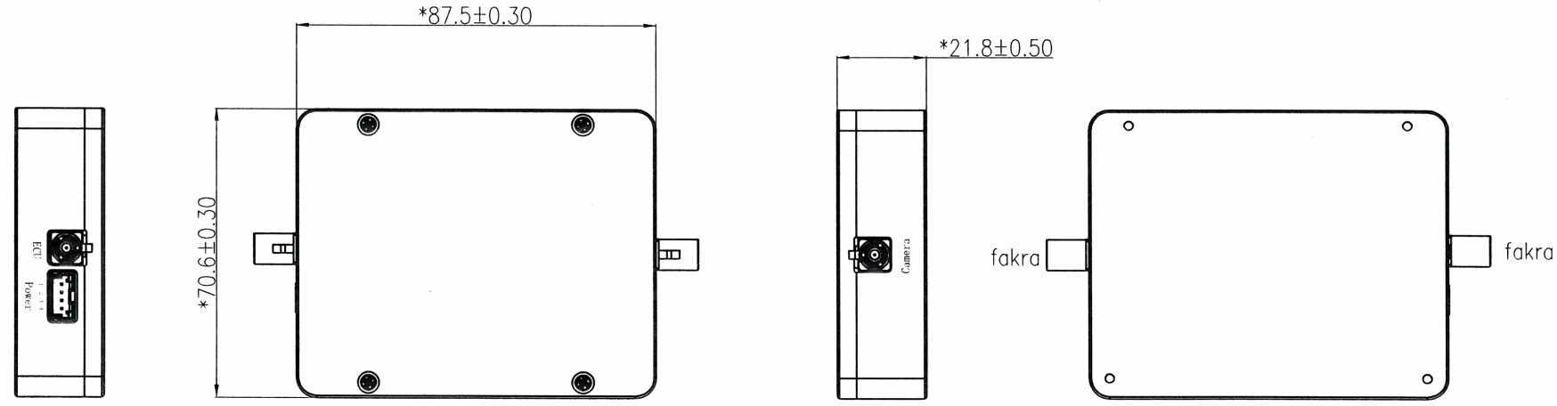
| Dimensions | 87.5mm × 70.6mm × 20mm |
| Color | Black |
| Weight | < 150g |
Dimensions
Hardware Overview
Block Diagram
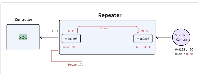
I2C Address Information
| Device | I2C Address (8-bit) | |
|---|---|---|
| 1 | Repeater: ECU | 0x80 |
| 2 | Repeater: Camera | 0x94 |
| 3 | SENSING Camera | 0x70 |
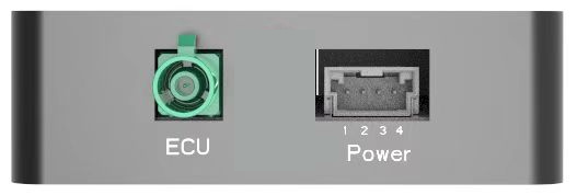
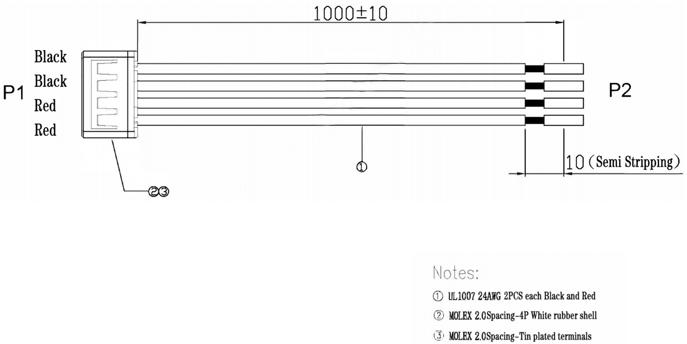
Connector Pin Definition
| Connector Component | Part Number | Manufacturer/Note |
|---|---|---|
| Repeater Device Connector | 50352-0400 | Molex |
| Cable Harness Connector | 50351-0400 | Molex |
| Power Supply | Pin3, Pin4 | 9~12V DC |
| Ground | Pin1, Pin2 | Common Ground |
Cable Harness Definition
Product Models
| Product Model | Input Channels | Output Channels | Resolution Support | Processor | Data Transfer Rate |
|---|---|---|---|---|---|
| SG2-BP0101-GMSL | 1CH | 1CH | Up to 1920×1080@30fps | MAX96705 | 1.5Gbps |
| SG8-BP0101-GMSL2 | 1CH | 1CH | Up to 3840×2160@30fps | MAX9295A | 6Gbps |
Getting Started
1. GMSL2 Camera Repeater Integration with Customer's Self-developed Platform
Using the Repeater when connecting to different domain controllers:
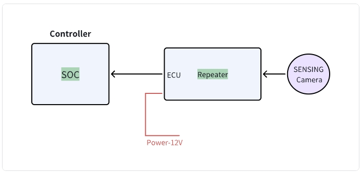
Repeater block diagram - Configuration for connecting to domain controllers
Operating Procedure
- Connect the system as shown in the diagram above.
- Power up the Repeater first.
- Initialize the Controller, which will power on and initialize the Repeater-ECU.
- Execute normal operation commands from the Controller to bring up the camera.
Operational Logic
- Upon receiving power, the Repeater device automatically configures the connected camera.
- Domain Controller only needs to configure the Repeater as if it were a camera, then trigger it normally to activate the imaging pipeline.
tip
Refer to the software flow and example code below to develop your custom driver implementation.
2. Controller Software Development Example Code
- Driver Development:
/* Example code for MAX9296 I2C initialization */
#define MAX9296_I2C_ADDR 0x90 // 8-bit address

int max9296_init() {
    // Initialize I2C bus
    i2c_init();

    // Disable MIPI output during configuration
    i2c_write(MAX9296_I2C_ADDR, 0x0313, 0x00);
    delay_ms(100);
    // Configure link settings for GMSL2 (6Gbps)
    i2c_write(MAX9296_I2C_ADDR, 0x0001, 0x02);

    // Configure linkA and linkB settings for GMSL2 selection (default value)
    i2c_write(MAX9296_I2C_ADDR, 0x0006, 0xC0);

    // Configure MIPI rate to 1200Mbps
    i2c_write(MAX9296_I2C_ADDR, 0x0320, 0x2C);

    // Enable MIPI output
    i2c_write(MAX9296_I2C_ADDR, 0x0313, 0x02);

    return 0;
}
- Repeater Configuration:
/* Example code for Repeater initialization */

#define MAX9295A_I2C_ADDR 0x80 // 8-bit address

int Splitter_init() {
    // Initialize deserializer first
    max9296_init();

    // Reset ISP
    i2c_write(MAX9295A_I2C_ADDR, 0x02BE, 0x10); // MFP0 high

    // Configure essential registers
    i2c_write(MAX9295A_I2C_ADDR, 0x0057, 0x12);
    i2c_write(MAX9295A_I2C_ADDR, 0x005B, 0x11);

    // Configure datatype to YUV422 8bit
    i2c_write(MAX9295A_I2C_ADDR, 0x0318, 0x5E);

    // Camera trigger sequence: MFP7 low to high
    i2c_write(MAX9295A_I2C_ADDR, 0x02D3, 0x00); // MFP7 low
    delay_ms(300);
    i2c_write(MAX9295A_I2C_ADDR, 0x02D3, 0x10); // MFP7 high

    // Initialize sensor,if without ISP, skip this step
    sensor_init();

    return 0;
}

int sensor_init() {
    // Initialize sensor
    i2c_write(sensor_I2C_ADDR, 0x0102, 0x0001);
    // Additional sensor initialization parameters
    // (Refer to Camera Information documentation for the complete sensor register configuration)
}
Integration Steps
-
BSP Integration:
- Modify the device tree to include the GMSL2 interface configuration
- Add the camera driver to kernel build configuration
- Configure the media controller pipeline for the camera
- Configure the Repeater-ECU
-
Application Development:
/* Example code for capturing camera frames */
#include "camera_api.h"

int main() {
    // Open camera device
    int fd = open("/dev/video0", O_RDWR);
    if (fd < 0) {
        perror("Failed to open camera device");
        return -1;
    }

    // Configure video capture format
    struct v4l2_format fmt = {0};
    fmt.type = V4L2_BUF_TYPE_VIDEO_CAPTURE;
    fmt.fmt.pix.width = 1920;
    fmt.fmt.pix.height = 1536;
    fmt.fmt.pix.pixelformat = V4L2_PIX_FMT_YUYV;

    if (ioctl(fd, VIDIOC_S_FMT, &fmt) < 0) {
        perror("Failed to set format");
        close(fd);
        return -1;
    }

    // Request and map buffers
    // ... (buffer setup code) ...

    // Start streaming
    // ... (streaming code) ...

    // Capture and process frames
    // ... (frame processing code) ...

    // Cleanup
    close(fd);
    return 0;
}
Step 2: Data Processing
After receiving the module data through the MIPI CSI interface:
- Data Reception
- GMSL2 protocol implementation
- Data rate configuration
- Image Processing Pipeline
- YUV422 8bit data parsing
- Image format conversion
Technical Support
-
Documentation
- Comprehensive register descriptions
- Integration guides
-
Engineering Support
- Technical consultation
- Debugging assistance
- Performance optimization
tip
SENSING Technology provides expert technical support for integration with most platforms. For detailed documentation, sample code, and technical assistance, please contact our support team.