Getting Started with GMSL2 Camera Splitter
Overview
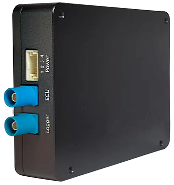
The GMSL2 Camera Splitter, engineered by SZ SENSING TECH CO.,LTD., enables a single GMSL input to be distributed to two GMSL outputs while maintaining identical data streams. This device is compatible with SENSING GMSL camera models.
- Lossless data transmission
- Full GMSL/GMSL2 compatibility
- Ultra-low latency (microsecond level)
- Minimal insertion loss
Specifications
| Parameter | Value |
|---|---|
| Transport Protocol | GMSL / GMSL2 |
| Input Ports | 1 |
| Output Ports | 2 |
| Input Interface | 1× GMSL2 |
| Output Interface | 2× GMSL2 |
| Supported Data Rates | 1.5Gbps, 3Gbps, 6Gbps |
| Maximum Resolution | Up to 3840×2160 |
| Output Synchronization Accuracy | < 10μs |
| Power Supply | Yes |
| Connector | Fakra Z Type |
| Operating Temperature Range | -40°C to +85°C |
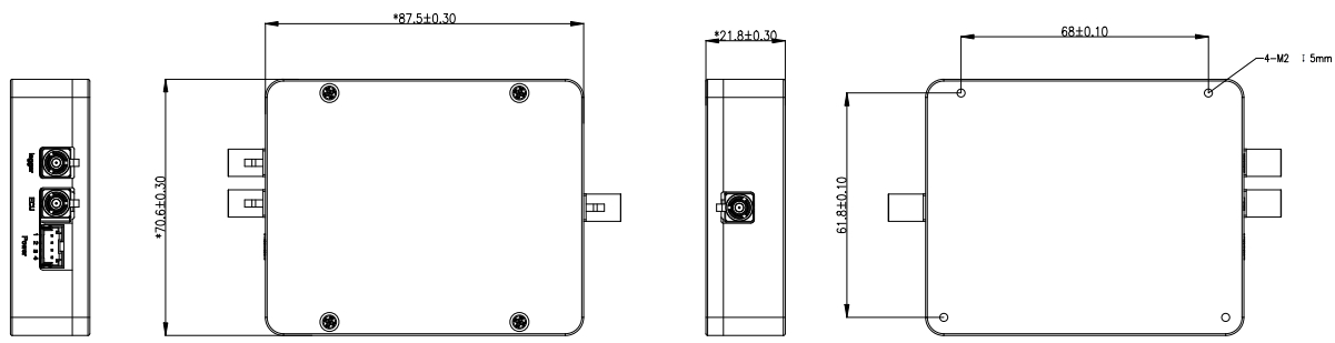
| Dimensions | 87.5mm × 70.6mm × 20mm |
| Color | Black |
| Weight | < 150g |
Dimensions
Hardware Overview
Block Diagram
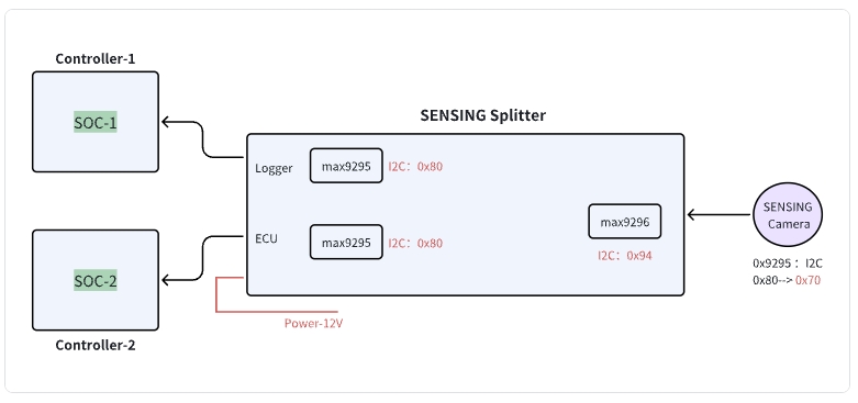
I2C Address Information
| Device | I2C Address (8-bit) | |
|---|---|---|
| 1 | Splitter: Logger | 0x80 |
| 2 | Splitter: ECU | 0x80 |
| 3 | Splitter: Camera | 0x94 |
| 4 | SENSING Camera | 0x70 |
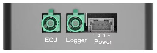
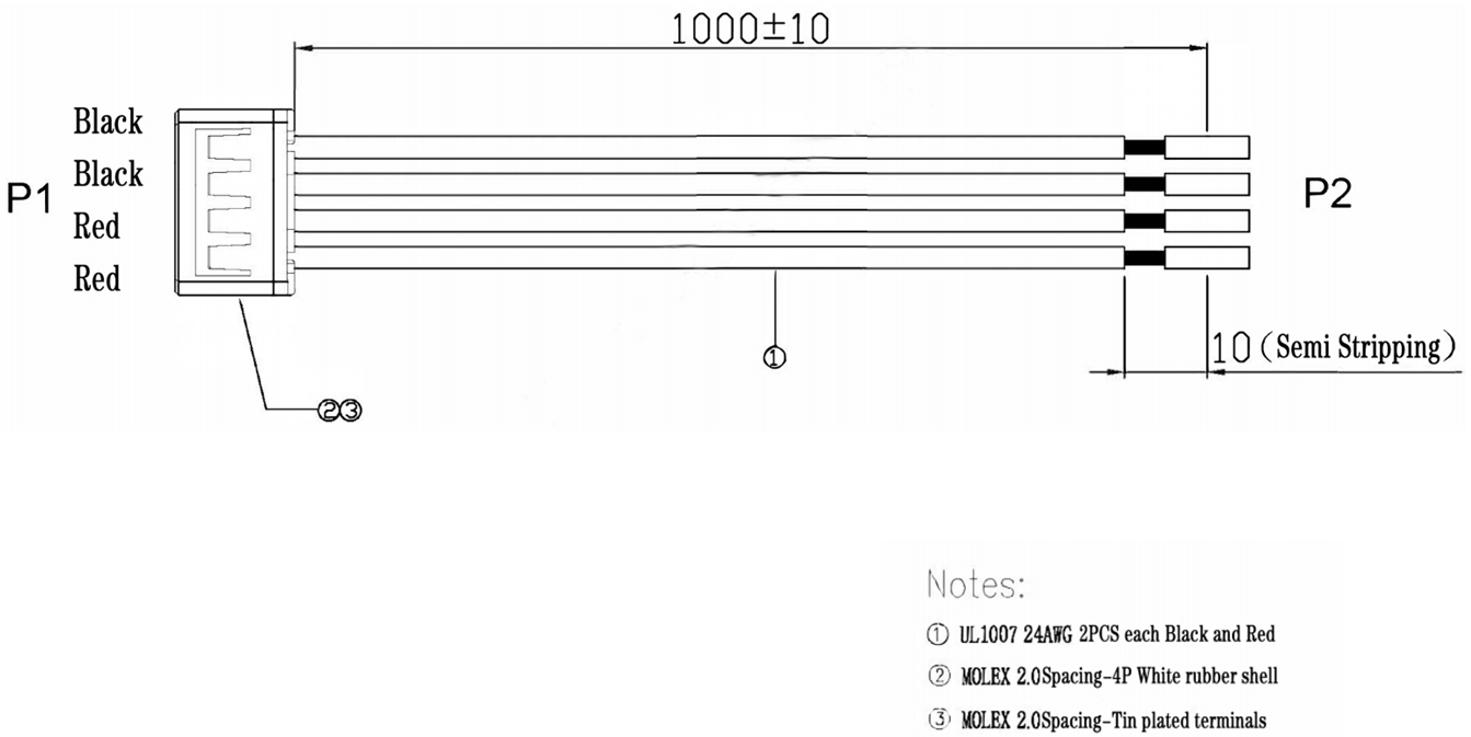
Connector Pin Definition
| Connector Component | Part Number | Manufacturer/Note |
|---|---|---|
| Splitter Device Connector | 50352-0400 | Molex |
| Cable Harness Connector | 50351-0400 | Molex |
| Power Supply | Pin3, Pin4 | 9~12V DC |
| Ground | Pin1, Pin2 | Common Ground |
Cable Harness Definition
Product Models
| Product Model | Input Channels | Output Channels | Resolution Support | Processor | Data Transfer Rate |
|---|---|---|---|---|---|
| SG2-BP0102-GMSL | 1CH | 2CH | Up to 1920×1080@30fps | MAX96705 | 1.5Gbps |
| SG8-BP0102-GMSL2 | 1CH | 2CH | Up to 3840×2160@30fps | MAX9295A | 6Gbps |
| SG8-BP0102-GMSL2F | 1CH | 2CH | Up to 1920×1080@30fps | MAX96717F | 3Gbps |
Getting Started
1. GMSL2 Camera Splitter Integration with Customer's Self-developed Platform
Using the Splitter when connecting to different domain controllers:
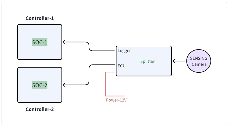
Splitter block diagram - Configuration for connecting to different domain controllers
Operating Procedure
- Connect the system as shown in the diagram above.
- Power up the Splitter first.
- Initialize the Controller 1, which will power on and initialize the Splitter-ECU, followed by the Controller 2 power-on sequence and initialize the Splitter-Logger.
- Execute normal operation commands from both Domain Controllers 1 and 2 to bring up the camera.
Operational Logic
- Upon receiving power, the Splitter device automatically configures the connected camera.
- Domain Controller 1 only needs to configure the Splitter as if it were a camera, then trigger it normally to activate the imaging pipeline.
Refer to the software flow and example code below to develop your custom driver implementation.
2. Controller Software Development Example Code
- Driver Development:
/* Example code for MAX9296 I2C initialization */
#define MAX9296_I2C_ADDR 0x90 // 8-bit address

int max9296_init() {
    // Initialize I2C bus
    i2c_init();

    // Disable MIPI output during configuration
    i2c_write(MAX9296_I2C_ADDR, 0x0313, 0x00);
    delay_ms(100);
    // Configure link settings for GMSL2 (6Gbps)
    i2c_write(MAX9296_I2C_ADDR, 0x0001, 0x02);

    // Configure linkA and linkB settings for GMSL2 selection (default value)
    i2c_write(MAX9296_I2C_ADDR, 0x0006, 0xC0);

    // Configure MIPI rate to 1200Mbps
    i2c_write(MAX9296_I2C_ADDR, 0x0320, 0x2C);

    // Enable MIPI output
    i2c_write(MAX9296_I2C_ADDR, 0x0313, 0x02);

    return 0;
}
- Splitter Configuration:
/* Example code for Splitter initialization */

#define MAX9295A_I2C_ADDR 0x80 // 8-bit address

int Splitter_init() {
    // Initialize deserializer first
    max9296_init();

    // Reset ISP
    i2c_write(MAX9295A_I2C_ADDR, 0x02BE, 0x10); // MFP0 high

    // Configure essential registers
    i2c_write(MAX9295A_I2C_ADDR, 0x0057, 0x12);
    i2c_write(MAX9295A_I2C_ADDR, 0x005B, 0x11);

    // Configure datatype to YUV422 8bit
    i2c_write(MAX9295A_I2C_ADDR, 0x0318, 0x5E);

    // Camera trigger sequence: MFP7 low to high
    i2c_write(MAX9295A_I2C_ADDR, 0x02D3, 0x00); // MFP7 low
    delay_ms(300);
    i2c_write(MAX9295A_I2C_ADDR, 0x02D3, 0x10); // MFP7 high

    // Initialize sensor,if without ISP, skip this step
    sensor_init();

    return 0;
}

int sensor_init() {
    // Initialize sensor
    i2c_write(sensor_I2C_ADDR, 0x0102, 0x0001);
    // Additional sensor initialization parameters
    // (Refer to Camera Information documentation for the complete sensor register configuration)
}
Integration Steps
-
BSP Integration:
- Modify the device tree to include the GMSL2 interface configuration
- Add the camera driver to kernel build configuration
- Configure the media controller pipeline for the camera
-
Application Development:
/* Example code for capturing camera frames */
#include "camera_api.h"

int main() {
    // Open camera device
    int fd = open("/dev/video0", O_RDWR);
    if (fd < 0) {
        perror("Failed to open camera device");
        return -1;
    }

    // Configure video capture format
    struct v4l2_format fmt = {0};
    fmt.type = V4L2_BUF_TYPE_VIDEO_CAPTURE;
    fmt.fmt.pix.width = 1920;
    fmt.fmt.pix.height = 1536;
    fmt.fmt.pix.pixelformat = V4L2_PIX_FMT_YUYV;

    if (ioctl(fd, VIDIOC_S_FMT, &fmt) < 0) {
        perror("Failed to set format");
        close(fd);
        return -1;
    }

    // Request and map buffers
    // ... (buffer setup code) ...

    // Start streaming
    // ... (streaming code) ...

    // Capture and process frames
    // ... (frame processing code) ...

    // Cleanup
    close(fd);
    return 0;
}
Step 2: Data Processing
After receiving the module data through the GMSL2 interface:
- Data Reception
- GMSL2 protocol implementation
- Data rate configuration
- Image Processing Pipeline
- YUV422 8bit data parsing
- Image format conversion
Technical Support
-
Documentation
- Comprehensive register descriptions
- Integration guides
-
Engineering Support
- Technical consultation
- Debugging assistance
- Performance optimization
SENSING Technology provides expert technical support for integration with most platforms. For detailed documentation, sample code, and technical assistance, please contact our support team.