Astra S56x Series Stereo Camera
Overview
The Astra S56x series is engineered specifically for embodied intelligence applications. It features dual 5MP Global Shutter image sensors and is developed with a high-reliability GMSL2 serial interface. The series is equipped with a 6-axis IMU and boasts a human-like 60mm baseline. It includes the S56 with a 130° Horizontal Field of View (HFOV) and the S56C with a 140° HFOV.
Astra S56x is the series name, not a specific model. The series includes S56 and S56C.

Model Selection and Differences
| Model | Lifecycle status | HFOV | Selection guidance |
|---|---|---|---|
| S56 | Legacy model—being phased out | 130°±3° | For existing projects and legacy support |
| S56C | Current recommended model | 140°±3° | Recommended for new projects; NVIDIA-recommended robotics stereo solution |
S56 and S56C differ only in lens parameters. Their hardware platform, interface, IMU, driver support, and platform compatibility are otherwise the same.
Key Features and Applications
Features:
• GMSL2 Coaxial Long-distance Transmission
• Global Shutter Technology
• Stereo Trigger Synchronization
• Integrated 6-axis IMU
Applications:
• Humanoid Robots
• Depth Computing
• VLA
• Data Acquisition
Getting Started
Specifications
| Parameter | Specification |
|---|---|
| QTY Of Sensor | 2 |
| Resolution | 2560 (H) × 1984 (V) |
| Frame Rate | 2560 × 1984 @30FPS |
| Shutter | Global shutter |
| Output Format | 10-bit RAW |
| Baseline | 60.00 ± 0.5 mm |
| Color / Mono | Color sensor |
| IMU | BMI088 |
| Camera Interface | GMSL2 |
| Power Supply | 9 - 16 VDC |
| Current | < 200mA |
| Connector | Amphenol (Z Type Fakra) |
| Operating Temp | -30~+70°C |
| Storage Temp | -30~+70°C |
| Dimensions | W: 30mm, L:84mm, H:25.44mm |
| Ingress Protection | IP52 |
| Weight | < 200g |
Lens Specifications
| Model | HFOV | VFOV | F.No | EFL (mm) | DOF |
|---|---|---|---|---|---|
| S56 | 130°±3° | 102°±3° | 2.0 | 2.18mm | 0.3~INF |
| S56C | 140°±3° | 102°±3° | 2.0 | 2.67mm | 0.4~INF |
Dimensions

Hardware Overview
Block Diagram

IMU: BMI088 (6-axis IMU)
The camera is equipped with a 6-axis IMU sensor, which provides accurate orientation and motion tracking information.
I2C Address Information
| Component | Parameter | Value |
|---|---|---|
| Serializer | Model | MAX9295D |
| I2C Address | 0x80 (8bit address) | |
| GMSL Rate | GMSL2 (6G bps) | |
| Sensor-1 | I2C Address | 0x20 (8bit address) |
| Frame Sync | Controlled by MAX9295D MFP7 | |
| Reset | Controlled by MAX9295D MFP3 | |
| Data Type | RAW 10bit | |
| Sensor-2 | I2C Address | 0x22 (8bit address) |
| Frame Sync | Controlled by MAX9295D MFP7 | |
| Reset | Controlled by MAX9295D MFP8 | |
| Data Type | RAW 10bit |
Employing Camera
1. Adaptation to NVIDIA® Jetson™ platform
NVIDIA Jetson AGX Orin

S56 / S56C Stereo Camera Connected to NVIDIA Jetson AGX Orin
Step 1: Installation Steps
- Connect the S56 or S56C stereo camera to the SG10A-AGON-G2M-A1 board using the coaxial cable
- Mount the SG10A-AGON-G2M-A1 board onto the Jetson AGX Orin module
- Connect power to the S56 or S56C stereo camera
- SG10A-AGON-G2M-A1 board Connect the power supply
- Power on the system
Step 2: Software Preparation
- Select the appropriate driver package based on your camera type and JetPack version
- Copy the full link address to DownGit to download
| NO. | JetPack Version | Camera | NVIDIA Jetson Devices | Adapter Board | SDK Download Link |
|---|---|---|---|---|---|
| 1 | JP6.2 | S56 / S56C stereo cameras | Jetson AGX Orin Developer Kit | SG10A-AGON-G2M-A1 | Download |
NVIDIA JetPack (Jetpack 5.1.2 or Jetpack 6.0 ) is the official software development kit (SDK) for the Jetson series of development boards. It includes the operating system, drivers, CUDA, cuDNN, TensorRT, and other development tools and libraries. Each JetPack version typically corresponds to a specific Jetson Linux version (formerly known as L4T - Linux for Tegra).
- 36.4.3: L4T R36.4.3 (Jetpack 6.2)
- 36.4: L4T R36.4 (Jetpack 6.1)
- 36.3: L4T R36.3 (Jetpack 6.0)
- 35.4.1: L4T R35.4.1 (Jetpack 5.1.2)
For more information, visit NVIDIA's official Jetson Download Center.
NVIDIA Jetson AGX Thor

Step 1: Installation Steps
- Following the labels in the image, connect the S56 or S56C stereo camera to the corresponding TRD1 G2A port using a coaxial cable.
- Connect CN7 to a DC 9-16V power supply.
- Power on the Jetson AGX Thor system.
Step 2: Software Preparation
- Select the appropriate driver package based on your camera type and JetPack version
- Copy the full link address to DownGit to download
| NO. | JetPack Version | Camera | NVIDIA Jetson Devices | SDK Download Link |
|---|---|---|---|---|
| 1 | JP7.0 | S56 / S56C stereo cameras | TRD1 G2A | Download |
2. Camera Integration with Customer's Self-developed Platform
For customers with their own deserializer who want to adapt our camera (serializer) to their platform, detailed technical coordination is required.
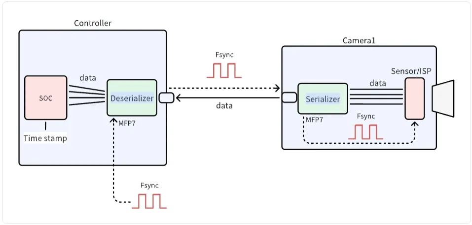
The diagram illustrates the communication architecture between a camera and controller system. It shows how data flows from the Sensor/ISP through the Serializer on the Camera side, across to the Deserializer and SOC on the Controller side. The system utilizes Fsync signals for synchronization and MFP7 interfaces for control. This architecture is essential for proper integration of SENSING cameras with customer-developed platforms.
Step 1: Link Register initialization
SENSING will provide:
-
Serializer and Deserializer Configuration
- Register configuration for the camera module-Getting Camera Information
- I2C communication protocol details
-
Link Status Troubleshooting Guide
- Link training parameters
- Error detection settings
Please refer to the software flow and demo code below to develop your driver code.
Software Development
- Driver Development:
/* Example code for MAX9296 I2C initialization */
#define MAX9296_I2C_ADDR 0x90 // 8-bit address

int max9296_init() {
    // Initialize I2C bus
    i2c_init();

    // disable MIPI output
    i2c_write(MAX9296_I2C_ADDR, 0x0313, 0x00);
    delay_ms(100);
    // Configure link settings for GMSL2 (6Gbps)
    i2c_write(MAX9296_I2C_ADDR, 0x0001, 0x02);

    // Configure linkA and linkB settings for GMSL2 selection (default value)
    i2c_write(MAX9296_I2C_ADDR, 0x0006, 0xC0);

    // Configure MIPI rate 1200Mbps
    i2c_write(MAX9296_I2C_ADDR, 0x0320, 0x2C);

    // enable MIPI output
    i2c_write(MAX9296_I2C_ADDR, 0x0313, 0x02);

    return 0;
}
- Camera Configuration:
/* Example code for   initialization */

#define MAX9295_I2C_ADDR 0x80 // 8-bit address

int camera_init() {
    // Initialize deserializer first
    max9296_init();

    // Reset ISP through MAX9295A
    i2c_write(0x80, 0x02BE, 0x10); // MFP0 high
    //
    i2c_write(0x80, 0x0057, 0x12);
    i2c_write(0x80, 0x005B, 0x11);
    //  Configure datatype  RAW10
    i2c_write(0x80, 0x0318, 0x6B);

    //  camera trigger  MFP7  low to  high
    i2c_write(0x80, 0x02D3, 0x00); // MFP7 low
    delay_ms(300);
    i2c_write(0x80, 0x02D3, 0x10); // MFP7 high

    return 0;
}
Integration Steps
-
BSP Integration:
- Modify the device tree to include the CSI interface configuration
- Add camera driver to kernel build configuration
- Configure media controller pipeline for the camera
-
Application Development:
/* Example code for capturing camera frames */
#include "camera_api.h"

int main() {
    // Open camera device
    int fd = open("/dev/video0", O_RDWR);
    if (fd < 0) {
        perror("Failed to open camera device");
        return -1;
    }

    // Configure video capture format
    struct v4l2_format fmt = {0};
    fmt.type = V4L2_BUF_TYPE_VIDEO_CAPTURE;
    fmt.fmt.pix.width = 1920;
    fmt.fmt.pix.height = 1536;
    fmt.fmt.pix.pixelformat = V4L2_PIX_FMT_RAW10;

    if (ioctl(fd, VIDIOC_S_FMT, &fmt) < 0) {
        perror("Failed to set format");
        close(fd);
        return -1;
    }

    // Request and map buffers
    // ... (buffer setup code) ...

    // Start streaming
    // ... (streaming code) ...

    // Capture and process frames
    // ... (frame processing code) ...

    // Cleanup
    close(fd);
    return 0;
}
Step 2: Data Processing
After receiving the module data through the MIPI CSI interface:
- Data Reception
- MIPI CSI-2 protocol implementation
- Data rate configuration
- Image Processing
- RAW10 data parsing
- Image format conversion
- Display configuration
Technical Support
-
Documentation
- Detailed register descriptions
-
Engineering Support
- Technical consultation
- Debug assistance
- Performance optimization
SENSING Technology provides technical support for integration with most platforms. For detailed documentation, sample code, and technical assistance, please contact our support team.