摄像头使用
本文介绍在不同平台和系统中使用 SENSING 摄像头的常见场景。每种集成方式都有对应的要求和技术注意事项。
1. 摄像头与客户自研平台集成
对于使用自有解串器并希望将我们的摄像头(串行器)适配到其平台的客户,需要进行详细的技术协同。
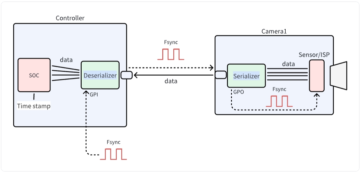
该图展示了摄像头与控制器系统之间的通信架构:数据从摄像头侧的传感器/ISP 经串行器传输到控制器侧的解串器和 SoC。系统使用 Fsync 信号进行同步,并通过控制接口完成控制。该架构是将 SENSING 摄像头正确集成到客户自研平台的关键。
步骤 1:链路寄存器初始化
SENSING 将提供:
-
串行器和解串器配置
-
寄存器配置 用于 摄像头模组-获取摄像头信息
-
I2C 通信协议细节
-
链路状态故障排查指南
-
链路训练参数
-
错误检测设置
提示
请参考下方软件流程和示例代码开发驱动代码。
软件开发(示例代码)
- 驱动开发:
/* Example code for UB954 I2C initialization */
#define UB954_I2C_ADDR 0x7A // 8 位地址

int ub954_init() {
    // Initialize I2C bus
    i2c_init();

    // reset UB954
    i2c_write(UB954_I2C_ADDR, 0x01, 0x02);
    delay_ms(100);
    // choose port0
    i2c_write(UB954_I2C_ADDR, 0x4C, 0x01);
    // choose linkA
    i2c_write(UB954_I2C_ADDR, 0x20, 0x20);

    i2c_write(UB954_I2C_ADDR, 0x58, 0x5E);
    // Set 953 I2C address alias
    i2c_write(UB954_I2C_ADDR, 0x5C, 0x30);
    // Set module I2C address
    i2c_write(UB954_I2C_ADDR, 0x5D, 0x20);
    // Set module I2C address alias
    i2c_write(UB954_I2C_ADDR, 0x65, 0x20);
    // Set MIPI lane rate to 800Mbps
    i2c_write(UB954_I2C_ADDR, 0x1F, 0x02);
    // Enable MIPI output, 4-lane, continuous clock mode
    i2c_write(UB954_I2C_ADDR, 0x33, 0x03);

    return 0;
}
- 摄像头 配置:
/* Example code for Camera initialization */
#define UB953_I2C_ADDR 0x30 // 8 位地址

int camera_init() {
    // Initialize deserializer first
    ub954_init();

    // Add: Reset 953
    i2c_write(UB953_I2C_ADDR, 0x01, 0x02); // // Reset 953
    delay_ms(100);                         // DELAY= 100
    i2c_write(UB953_I2C_ADDR, 0x02, 0x73); // MIPI 4-lane, continuous clock mode
    i2c_write(UB953_I2C_ADDR, 0x0D, 0xD2); // GPIO1 high to reset module (if available)

    // camera trigger low to high
    i2c_write(UB953_I2C_ADDR, 0x0E, 0x3C); // GPIO0 output
    delay_ms(500);                         // DELAY=500ms
    i2c_write(UB953_I2C_ADDR, 0x0D, 0xC2);  // GPIO0 low
    delay_ms(500);                         // DELAY=500ms
    i2c_write(UB953_I2C_ADDR, 0x0D, 0xC3); // GPIO0 high

    return 0;
}
集成步骤
- BSP 集成:
- 修改设备树以包含 CSI 接口配置
- 将摄像头驱动加入内核构建配置
- 配置用于摄像头的 media controller pipeline
- 应用开发:
/* Example code for capturing camera frames */
#include "camera_api.h"

int main() {
    // Open camera device
    int fd = open("/dev/video0", O_RDWR);
    if (fd < 0) {
        perror("Failed to open camera device");
        return -1;
    }

    // Configure video capture format
    struct v4l2_format fmt = {0};
    fmt.type = V4L2_BUF_TYPE_VIDEO_CAPTURE;
    fmt.fmt.pix.width = 1920;
    fmt.fmt.pix.height = 1080;
    fmt.fmt.pix.pixelformat = V4L2_PIX_FMT_YUYV;

    if (ioctl(fd, VIDIOC_S_FMT, &fmt) < 0) {
        perror("Failed to set format");
        close(fd);
        return -1;
    }

    // Request and map buffers
    // ... (buffer setup code) ...

    // Start streaming
    // ... (streaming code) ...

    // Capture and process frames
    // ... (frame processing code) ...

    // Cleanup
    close(fd);
    return 0;
}
步骤 2:数据处理
通过 MIPI CSI 接口接收模组数据后:
- 数据接收
- 实现 MIPI CSI-2 协议
- 数据速率配置
- 时钟同步
- 图像处理
- Raw/YUV 数据解析
- 图像格式转换
- 显示配置
技术支持
- 文档
- 详细寄存器说明
- 时序图
- 上电时序图
- 工程支持
- 技术咨询
- 调试协助
- 性能优化
提示
SENSING Technology 为大多数平台的集成提供技术支持。如需详细文档、示例代码和技术协助,请联系我们的支持团队。