Employing Camera
This guide describes different scenarios for employing our cameras in various platforms and systems. Each integration method has its specific requirements and technical considerations.
1. Camera Integration with Customer's Self-developed Platform
For customers with their own deserializer who want to adapt our camera (serializer) to their platform, detailed technical coordination is required.
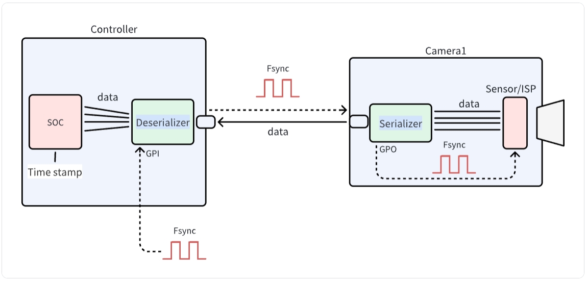
The diagram illustrates the communication architecture between a camera and controller system. It shows how data flows from the Sensor/ISP through the Serializer on the Camera side, across to the Deserializer and SOC on the Controller side. The system utilizes Fsync signals for synchronization and GPI interfaces for control. This architecture is essential for proper integration of SENSING cameras with customer-developed platforms.
Step 1: Link Register initialization
SENSING will provide:
-
Serializer and Deserializer Configuration
- Register configuration for the camera module-Getting Camera Information
- I2C communication protocol details
-
Link Status Troubleshooting Guide
- Link training parameters
- Error detection settings
Please refer to the software flow and demo code below to develop your driver code.
Software Development (Demo Code)
- Driver Development:
/* Example code for UB954 I2C initialization */
#define UB954_I2C_ADDR 0x7A // 8-bit address

int ub954_init() {
    // Initialize I2C bus
    i2c_init();

    // reset UB954
    i2c_write(UB954_I2C_ADDR, 0x01, 0x02);
    delay_ms(100);
    // choose port0
    i2c_write(UB954_I2C_ADDR, 0x4C, 0x01);
    // choose linkA
    i2c_write(UB954_I2C_ADDR, 0x20, 0x20);

    i2c_write(UB954_I2C_ADDR, 0x58, 0x5E);
    // Set 953 I2C address alias
    i2c_write(UB954_I2C_ADDR, 0x5C, 0x30);
    // Set module I2C address
    i2c_write(UB954_I2C_ADDR, 0x5D, 0x20);
    // Set module I2C address alias
    i2c_write(UB954_I2C_ADDR, 0x65, 0x20);
    // Set MIPI lane rate to 800Mbps
    i2c_write(UB954_I2C_ADDR, 0x1F, 0x02);
    // Enable MIPI output, 4-lane, continuous clock mode
    i2c_write(UB954_I2C_ADDR, 0x33, 0x03);

    return 0;
}
- Camera Configuration:
/* Example code for Camera initialization */
#define UB953_I2C_ADDR 0x30 // 8-bit address

int camera_init() {
    // Initialize deserializer first
    ub954_init();

    // Add: Reset 953
    i2c_write(UB953_I2C_ADDR, 0x01, 0x02); // // Reset 953
    delay_ms(100);                         // DELAY= 100
    i2c_write(UB953_I2C_ADDR, 0x02, 0x73); // MIPI 4-lane, continuous clock mode
    i2c_write(UB953_I2C_ADDR, 0x0D, 0xD2); // GPIO1 high to reset module (if available)

    // camera trigger low to high
    i2c_write(UB953_I2C_ADDR, 0x0E, 0x3C); // GPIO0 output
    delay_ms(500);                         // DELAY=500ms
    i2c_write(UB953_I2C_ADDR, 0x0D, 0xC2);  // GPIO0 low
    delay_ms(500);                         // DELAY=500ms
    i2c_write(UB953_I2C_ADDR, 0x0D, 0xC3); // GPIO0 high

    return 0;
}
Integration Steps
-
BSP Integration:
- Modify the device tree to include the CSI interface configuration
- Add camera driver to kernel build configuration
- Configure media controller pipeline for the camera
-
Application Development:
/* Example code for capturing camera frames */
#include "camera_api.h"

int main() {
    // Open camera device
    int fd = open("/dev/video0", O_RDWR);
    if (fd < 0) {
        perror("Failed to open camera device");
        return -1;
    }

    // Configure video capture format
    struct v4l2_format fmt = {0};
    fmt.type = V4L2_BUF_TYPE_VIDEO_CAPTURE;
    fmt.fmt.pix.width = 1920;
    fmt.fmt.pix.height = 1080;
    fmt.fmt.pix.pixelformat = V4L2_PIX_FMT_YUYV;

    if (ioctl(fd, VIDIOC_S_FMT, &fmt) < 0) {
        perror("Failed to set format");
        close(fd);
        return -1;
    }

    // Request and map buffers
    // ... (buffer setup code) ...

    // Start streaming
    // ... (streaming code) ...

    // Capture and process frames
    // ... (frame processing code) ...

    // Cleanup
    close(fd);
    return 0;
}
Step 2: Data Processing
After receiving the module data through the MIPI CSI interface:
- Data Reception
- MIPI CSI-2 protocol implementation
- Data rate configuration
- Clock synchronization
- Image Processing
- Raw/YUV data parsing
- Image format conversion
- Display configuration
Technical Support
- Documentation
- Detailed register descriptions
- Timing diagrams
- Power sequence diagrams
- Engineering Support
- Technical consultation
- Debug assistance
- Performance optimization
SENSING Technology provides technical support for integration with most platforms. For detailed documentation, sample code, and technical assistance, please contact our support team.