PANDA Serial PG2 Application
1. Device Connection and Startup
1.1 Device Connection
Connect the SENSING Camera to the cam1 interface of the PANDA Serial PG2 using the USB 3.0 cable, then connect to your PC as illustrated in the connection diagram. Use the SensingCaptureV3 software tool to display camera images and perform camera upgrades.
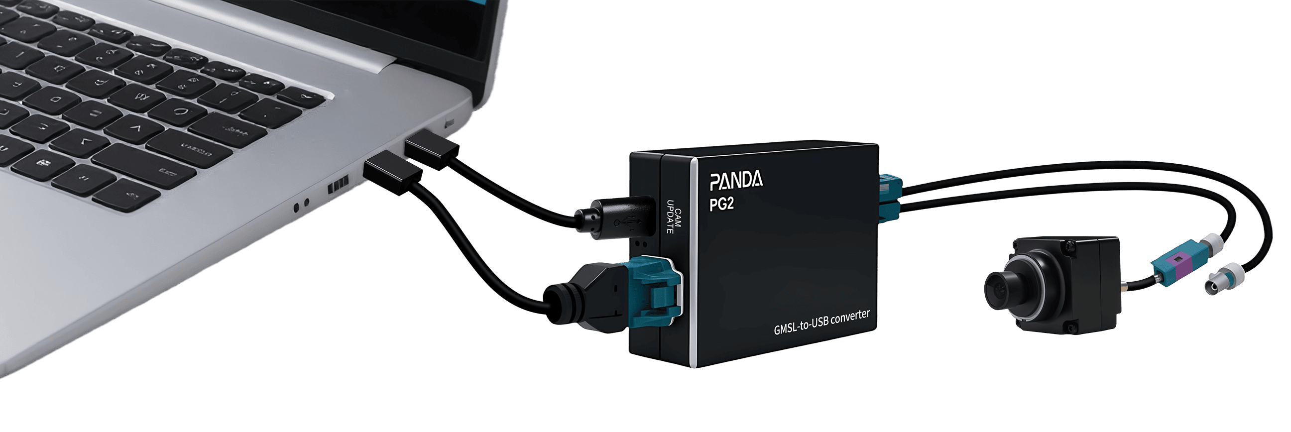
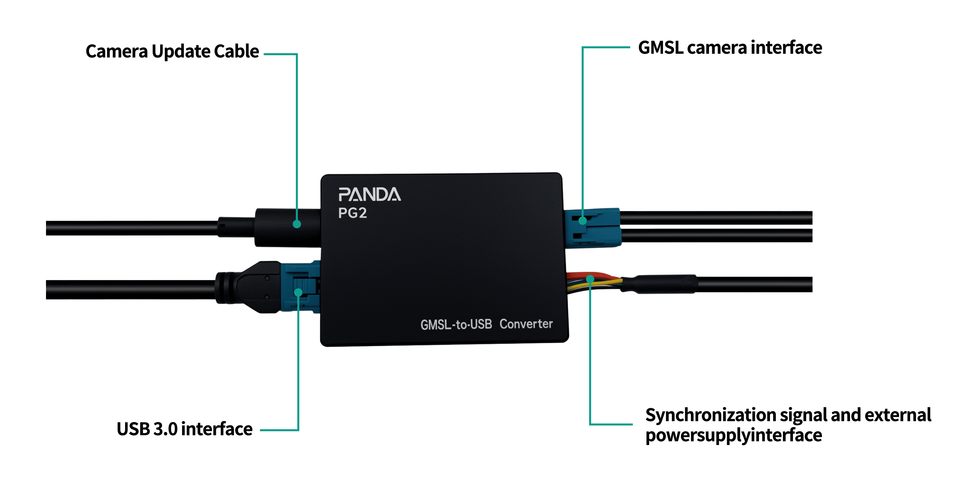
PANDA Serial PG2 Installation Connection Diagram
1.2 Hardware Environment Check (Windows Platform)
The PANDA Serial PG2 follows the UVC protocol specification defined by USB-IF. It can be used immediately after plugging in and is default-free (using the UVC camera driver provided by Windows). It should be noted that the PG2 only supports the USB3.0 interface. After connecting the PG2 to the USB 3.0 interface of the PC, the device can be seen in the Facility Management of the window. Open the device manager of the computer. You can see the "SENSING_USB3_CAMERA" device item in the camera project of the device manager, and you can see the FT4222 device item in the Universal Serial Bus Controller project,when the CAM UPDATE port is connected to the computer.
SensingCaptureV3 Installation Instructions
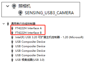
Hardware Environment Check
1.3 Software Installation
Download Link: https://github.com/SENSING-Technology/SensingCaptureV3
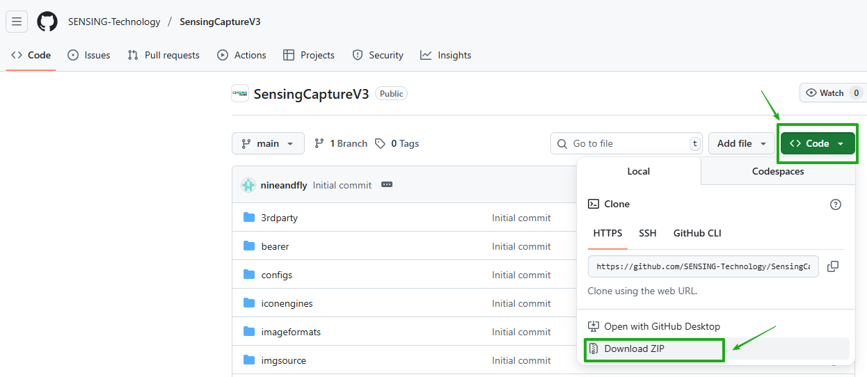
SensingCaptureV3 Download
After downloading SensingCaptureV3, follow steps 1-3 as shown in the accompanying images to install and use the software.
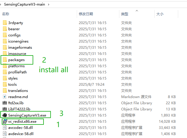
SensingCaptureV3 Installation Instructions
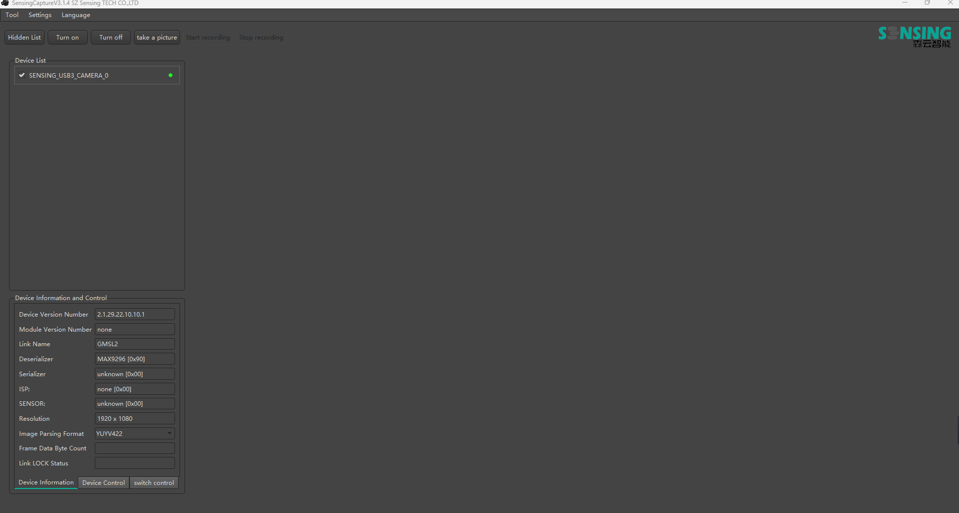
Figure 1: SensingCaptureV3 startup interface showing the main control panel and display area
1.4 Camera bringup operation
1.4.1 Launch SensingCaptureV3
In the device list, the device number and control panel will display information about the currently connected camera.
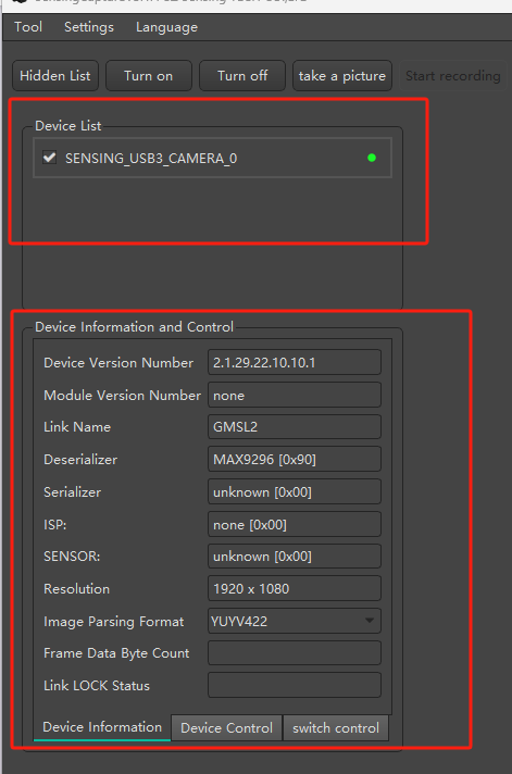
Figure 3: Device list showing connected camera information
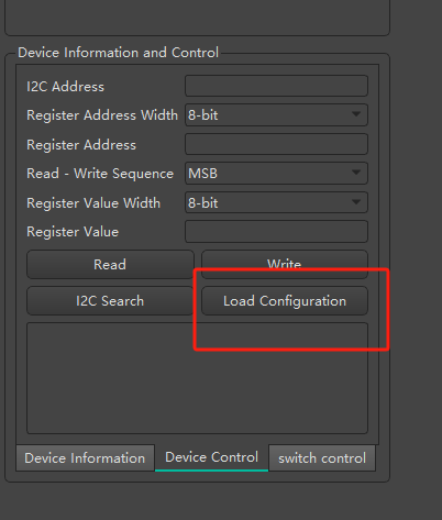
Figure 4: Camera control panel with configuration options
1.4.2 Add Configuration
In the device information and control panel, click "Device Control", select "Add Configuration" as shown in Figure 4. The system will display the configuration file, which can be added using two methods:
Method 1: In the configuration file, click the three dots, select the camera's corresponding configuration file in the dropdown menu, as shown in Figure 5.
Method 2: In the search mode, enter partial information of the configuration file name. According to the configuration file naming convention: Product Model_Resolution@Frame Rate_Image Format, enter partial information such as ISX031, as shown in Figure 6.
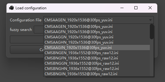
Figure 5: Configuration file selection dropdown menu
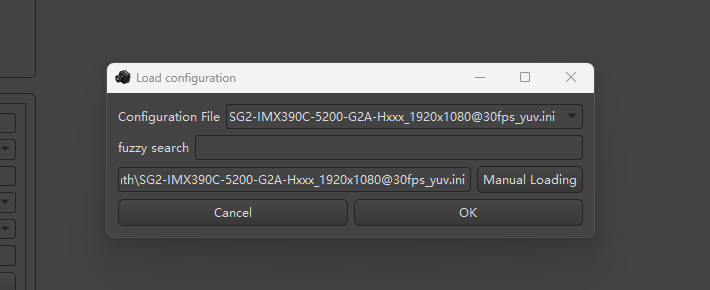
Figure 6: Search configuration file by entering partial name (e.g., ISX031)
After selecting the configuration file, click "Confirm". The system will automatically load the detailed information of the configuration file and complete the loading process. The system will then display the information shown in Figure 7.
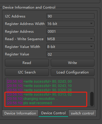
Figure 7: Configuration file successfully loaded with detailed camera parameters displayed
1.4.3 Start Camera
Click "Start Camera" in the upper left corner. The software will display real-time captured images in the middle area, as shown in Figure 8.
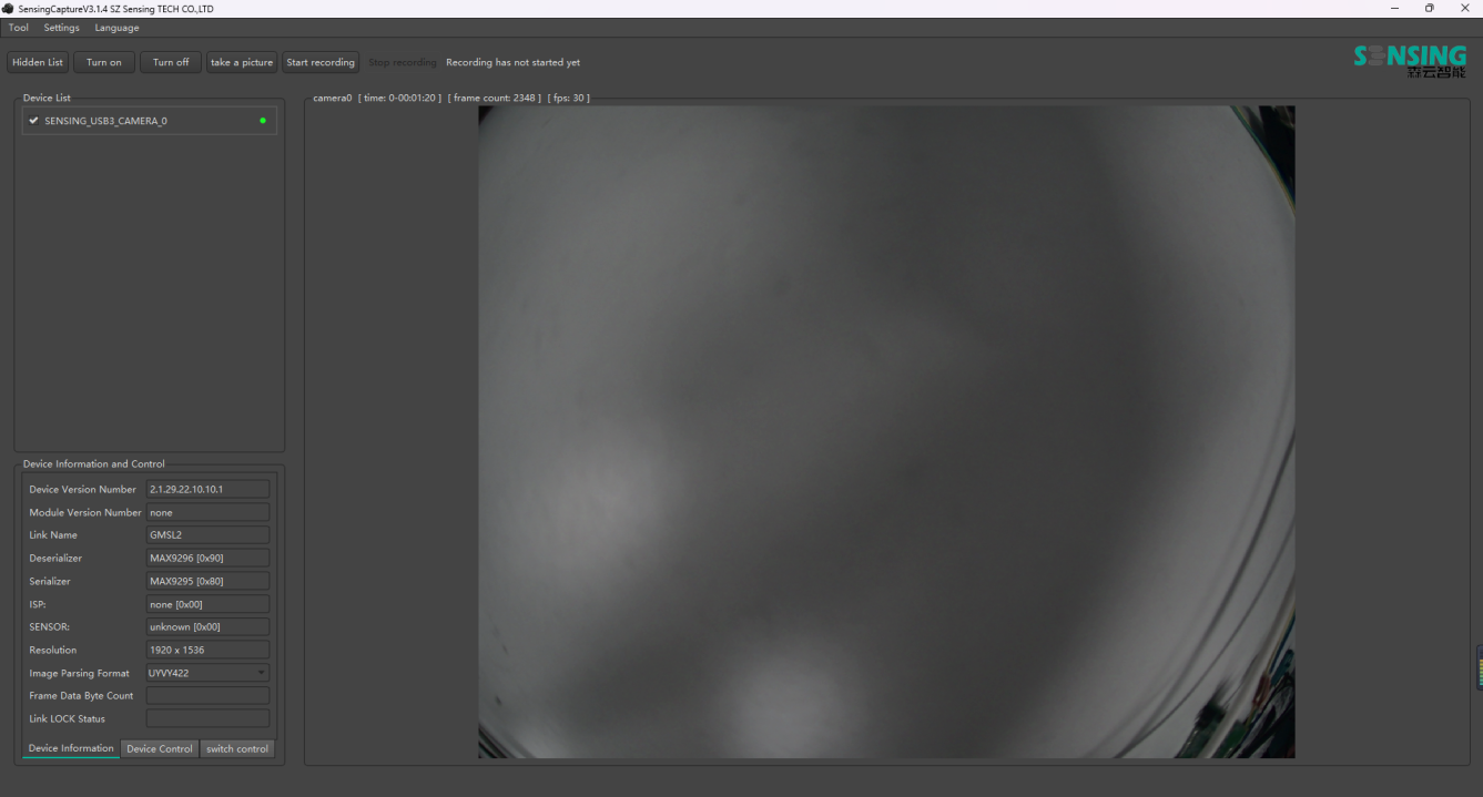
Figure 8: Live camera view displaying real-time captured images with control panel on the left
2. Functionality Description
2.1 Recording Function
2.1.1 Start Recording
Open the camera and the interface will display as shown in Figure 9. Click "Start Recording", and the system will automatically create a storage path for video recording. Based on personal needs, establish a reasonable storage path. At this point, the interface will display a "Recording" prompt, indicating that recording is in progress. The recorded video file is saved in AVI format (Audio Video Interleave), with the file extension .avi. The recording format is Motion-JPEG (MJPEG).
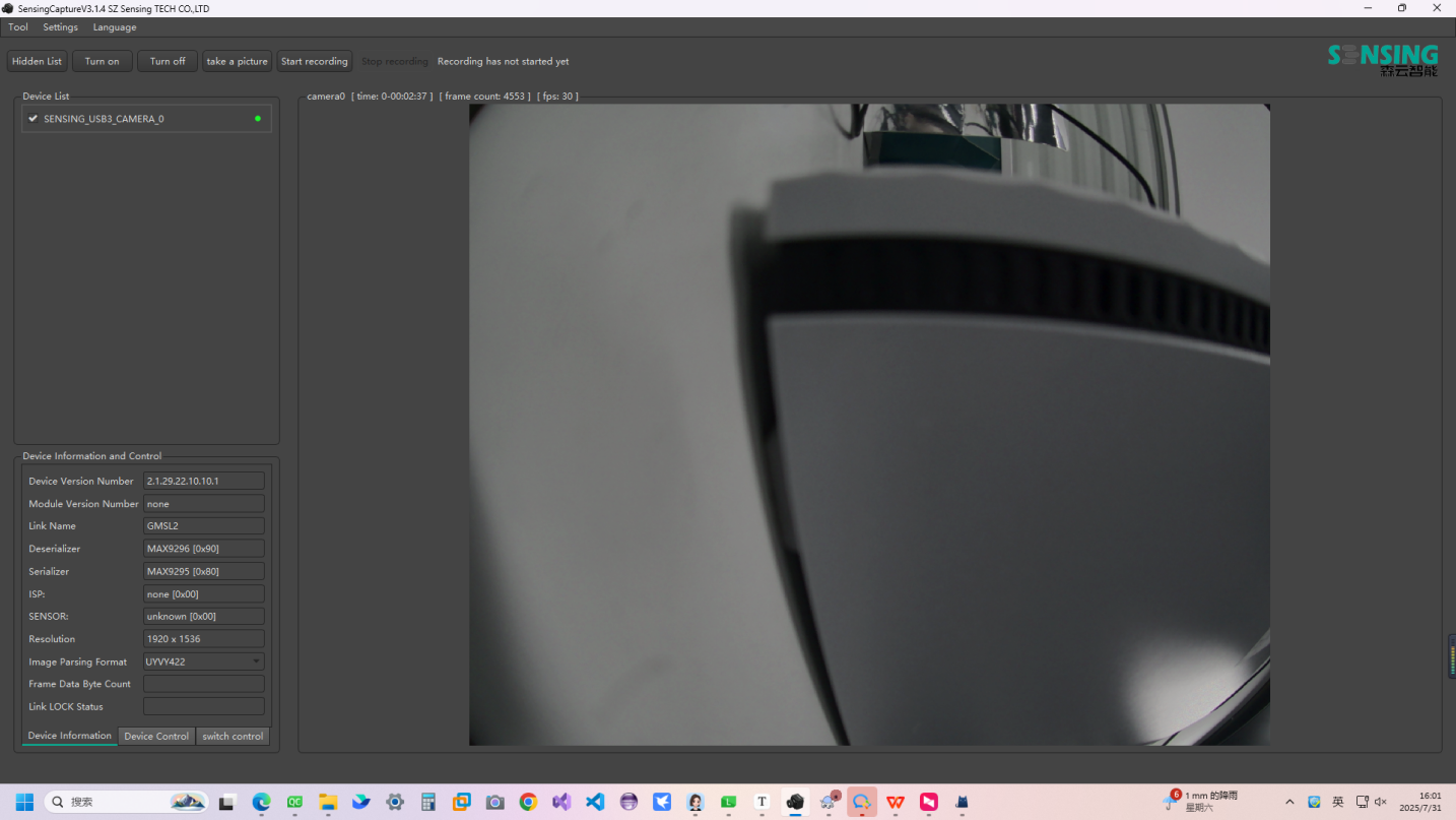
Figure 9: Camera interface with "Start Recording" button highlighted, showing live video feed
2.1.2 Stop Recording
Click "Stop Recording", and the interface will display as shown in Figure 10. This will immediately stop recording. In the established storage path, you can find the recorded video.
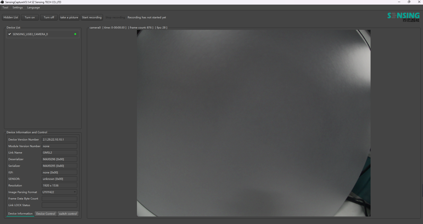
Figure 10: Interface showing "Stop Recording" option with file directory highlighted
2.2 Snapshot Function
Open the camera and click "Snapshot". The interface will display as shown in Figure 11. Immediately after taking the snapshot, the file will be saved in the software's installation directory under the pictures folder, as shown in Figure 12.
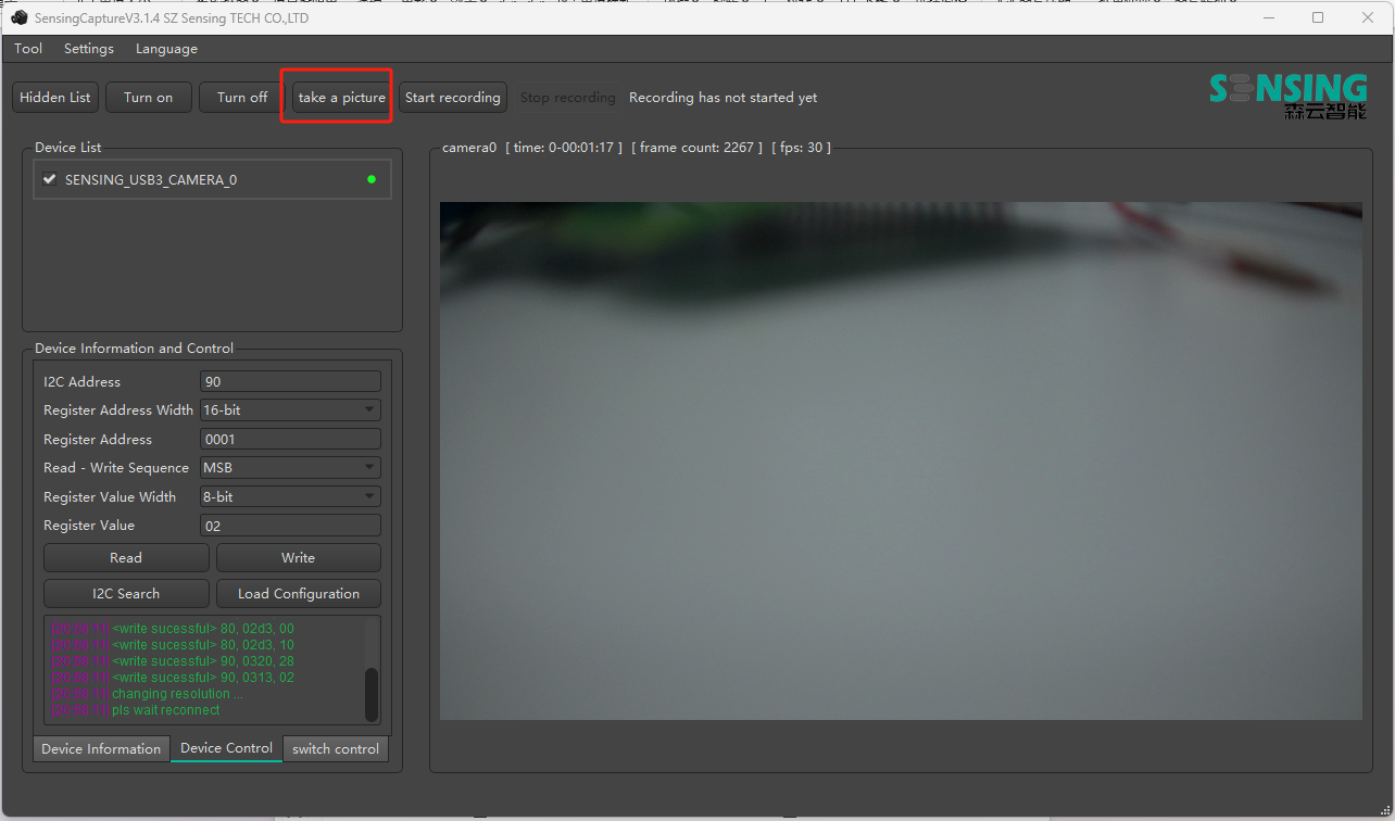
Figure 11: Camera interface with snapshot function activated
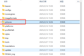
Figure 12: File directory showing saved snapshot in the pictures folder
2.3 Image Component Testing and Updates
2.3.1 Confirm Successful Connection
Open the camera component and connect it to the camera via USB data cable. Ensure the Type C cable connection is complete, as shown in Figure 2.
2.3.2 Select ISP Type and Firmware Component
During the testing process, click the tool-camera component upgrade button. Select the required camera sensor or ISP type, and proceed with the firmware upgrade. If you need to obtain the camera type number SG3-ISX031C-G2A-H190XA, please refer to the ISP type selection process.
For Sony cameras, click the measurement button. You need to add a corresponding component to obtain the version number. The operation steps are as shown in Figure 13. After the measurement, the version number is recorded.
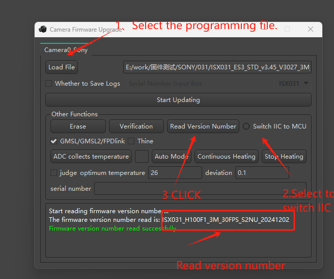
Figure 13: Sony camera component configuration interface showing measurement and version detection options
2.3.3 Update Components
The update process involves the following steps:
(1) Add the required update components
(2) Select IIC function and MCU
(3) Click the left health update button
For specific operations, refer to Figure 14. After the component is completed, click to read the version number. If the version has been successfully updated, the component upgrade is successful, as shown in Figure 15.
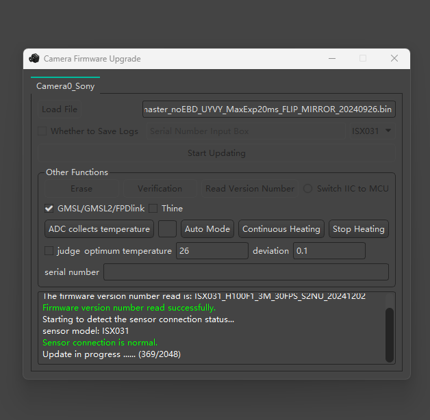
Figure 14: Component update interface showing configuration options and update controls
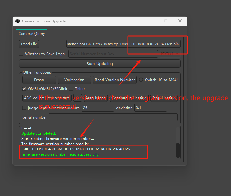
Figure 15: Update completion status showing successful component upgrade
2.4 Register Configuration
Perform operations in the device information and control panel, taking SG3S-ISX031C-GMSL2F-H190XA as an example:
2.4.1 Configure I2C Address
According to product specifications, use hardware configuration pages to check the product's I2C address. For example, perform address 96717F. The default input 8-bit address is 0x80. You need to enter the I2C address internally as 0x80. The address is an 8-bit I2C address.
2.4.2 Select Storage Depth
Select the corresponding storage depth according to requirements. Currently supports 8bit and 16bit formats. The storage depth of 96717F is 16bit. You can check the product specifications, use hardware configuration pages, or refer to the 96717F DATASHEET.
2.4.3 Configure Storage Address
According to the required storage address, enter it in the text field. For example, the storage address for configuration is 0X02D3. Enter 02D3.
When reading in sequence: In the read and write sequence, select the required sequence. You can select any position in the middle or low-order priority. MSB represents high-order priority, LSB represents low-order priority. This setting is MSB.
2.4.4 Select Storage Depth Value
In the storage depth value selection, choose 8-bit or 16-bit as the internal storage depth value. For 96717F, it is 8-bit.
2.4.5 Input Operation Storage Value
In the storage value field, input the required value. This should be 0X02D3, input 0x10. The actual 96717F GPIO 7 is used as output and pulled high.
2.4.6 Read Operation
Click the read button. If the operation is successful, it will display the value as shown in Figure 16. Green text <read successful> 80, 02d3, 83 indicates successful reading. Red text <read fail> 80, 02d3, err indicates reading failure.
2.4.7 Write Operation
Click the write button to send the value to the storage location, as shown in Figure 17. Green text <write successful> 80, 02d3, 10 indicates successful writing. Red text <write fail> 80, 02d3, 10 indicates writing failure.
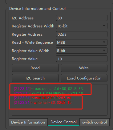
Figure 16: Register read/write interface showing I2C address, storage depth, and operation status messages
2.5 External Trigger
According to Figure 2's connection setup, as shown in Figure 17, the P2 pin trigger input will externally trigger the signal transmission to the MAX9296's MP7 pin. External trigger input supports 1.8V or 3.3V voltage levels. External trigger is required, and you need to add Figure 18's external trigger status. The power supply is also external trigger.
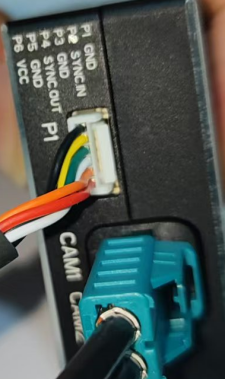
Figure 17: External trigger hardware connection showing P2 pin and cable setup
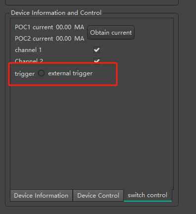
Figure 18: External trigger software configuration interface with trigger mode settings
2.6 Reading Current
When the camera is connected to the UVC box, the current reading method can be used to estimate the camera's power consumption. Click the button to obtain the current, and you can check the current status of the camera, as shown in Figure 19.
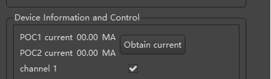
Figure 19: Current reading interface displaying camera power consumption measurements
2.7 Camera Internal Parameter Reading
If the camera has internal parameter standards, you can use the position reading internal parameter function to read the camera's internal parameter output.
Click the tool bar, select OTP burning. Select the camera type according to the OTP type interface and select the corresponding response, as shown in Figure 20.
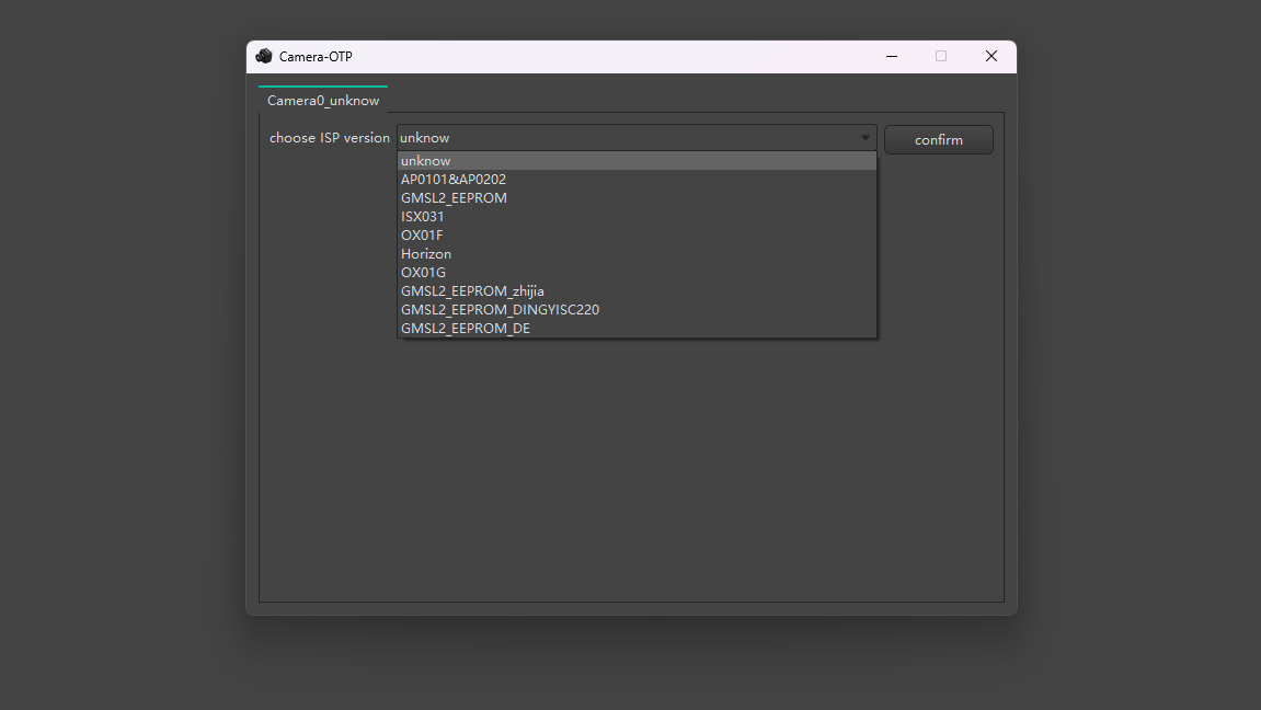
Figure 20: Camera OTP type selection interface showing available camera types including unknown, AR0147, IMX390002, IMX412, ZEPROM, OV9281, and OV9734
After selection is complete, click confirm, and Figure 21's interface will appear. Click read, wait for Figure 22 to appear, and the internal parameter data will be displayed.
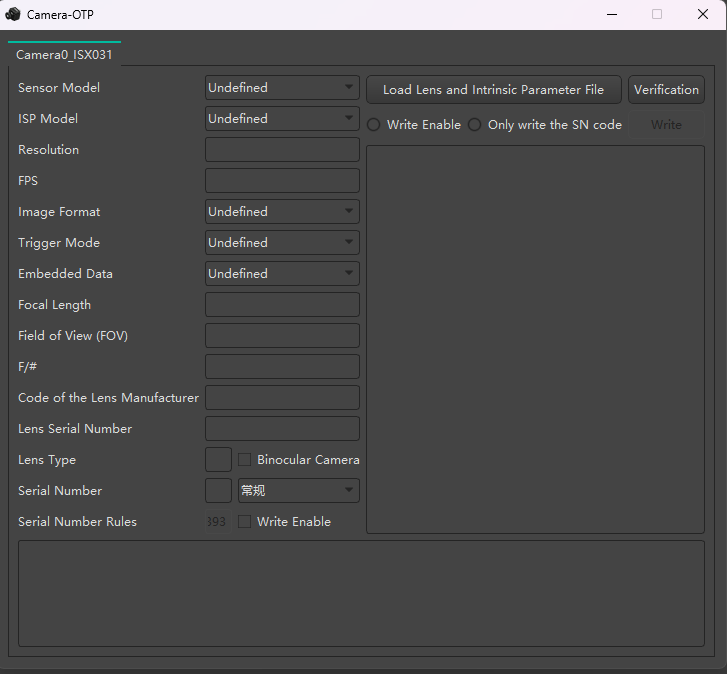
Figure 21: OTP parameter reading interface with read button highlighted
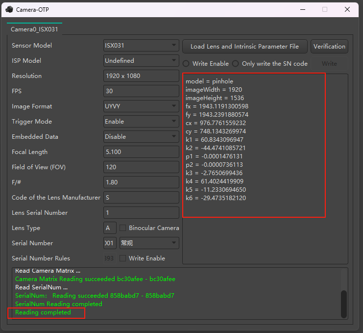
Figure 22: OTP parameter data display showing detailed camera internal parameters
2.8 PANDA Box Firmware Update
First, you need to install the driver. The driver is located in the user directory under 3rdparty/DriverInstallerCyUSB3.
2.8.1 Hardware Connection and Boot Mode Setup
Step 1: As shown in Figure 23, position the device with four buttons, press and hold the button (boot mode), then connect the USB 3.0 interface to the computer (ensure the computer's USB interface supports the underlying technology).
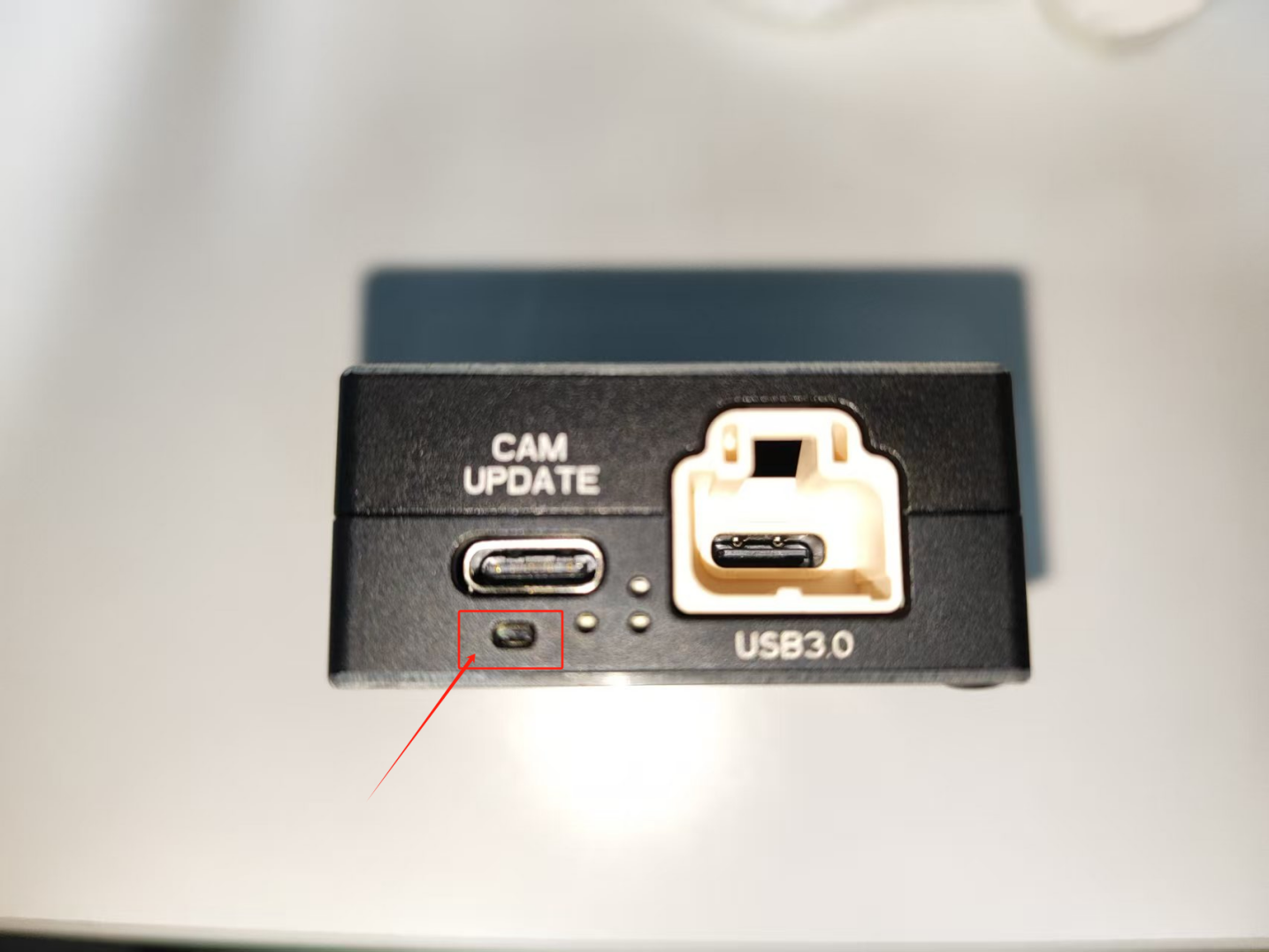
Figure 23: PANDA box hardware showing CAM UPDATE interface with USB3.0 connection and boot button location
Step 2: Open the position, on the left side, in the settings, select the device upgrade level, as shown in Figure 24's position display.
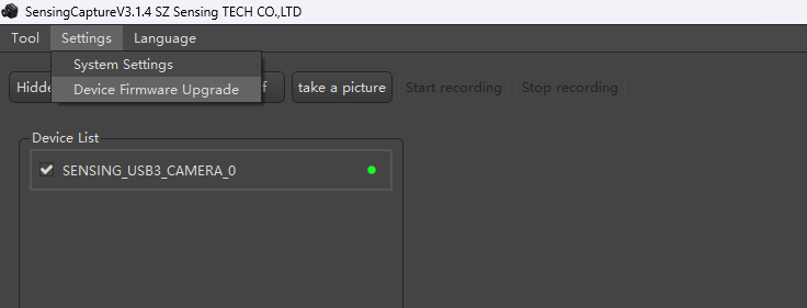
Figure 24: SensingCapture software interface showing device upgrade settings with firmware update options
Step 3: If you recognize the device and open the level mode, you can export the Cypress FX3 from the exported interface on the left side.
2.8.2 USB Control Center Operations
Step 4: As shown in Figure 26, open the level interface, select I2C EEPROM, after selection, the interface will output the selected bounce, select the required level firmware, click open.
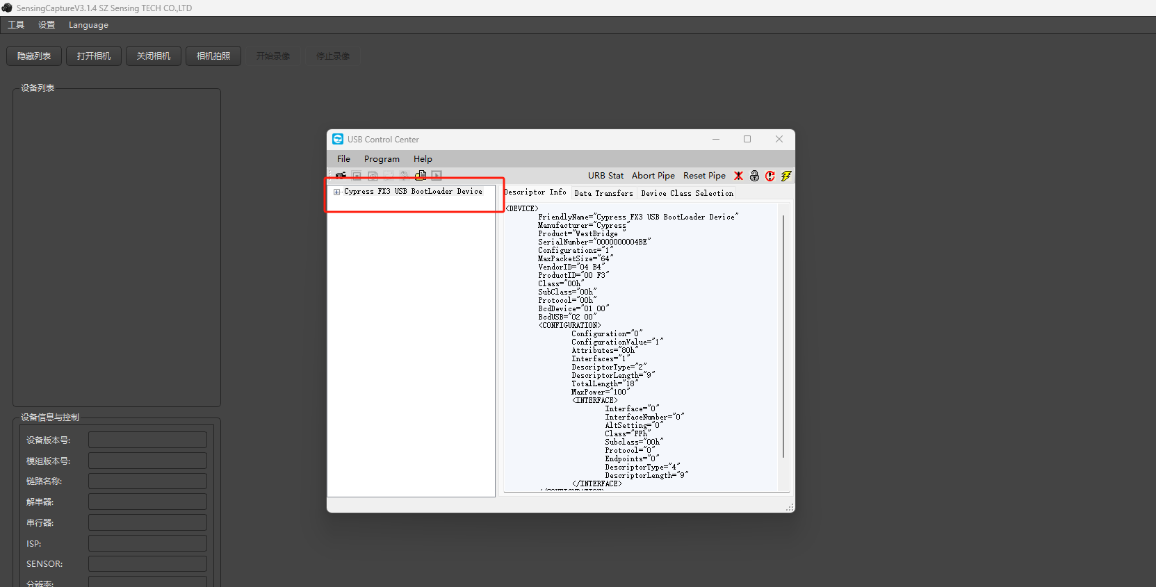
Figure 25: USB BootLoader device detection interface showing device recognition and firmware update preparation
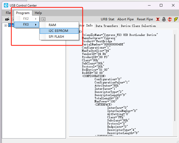
Figure 26: USB Control Center interface showing I2C EEPROM selection with firmware file options including FX3, RAM, I2C EEPROM, and SPI FLASH
Step 5: After completion, as shown in Figure 28, wait for the download to show the upgrade level, wait for the display as shown in Figure 29 to show "Succeeded", indicating the upgrade level is successful.
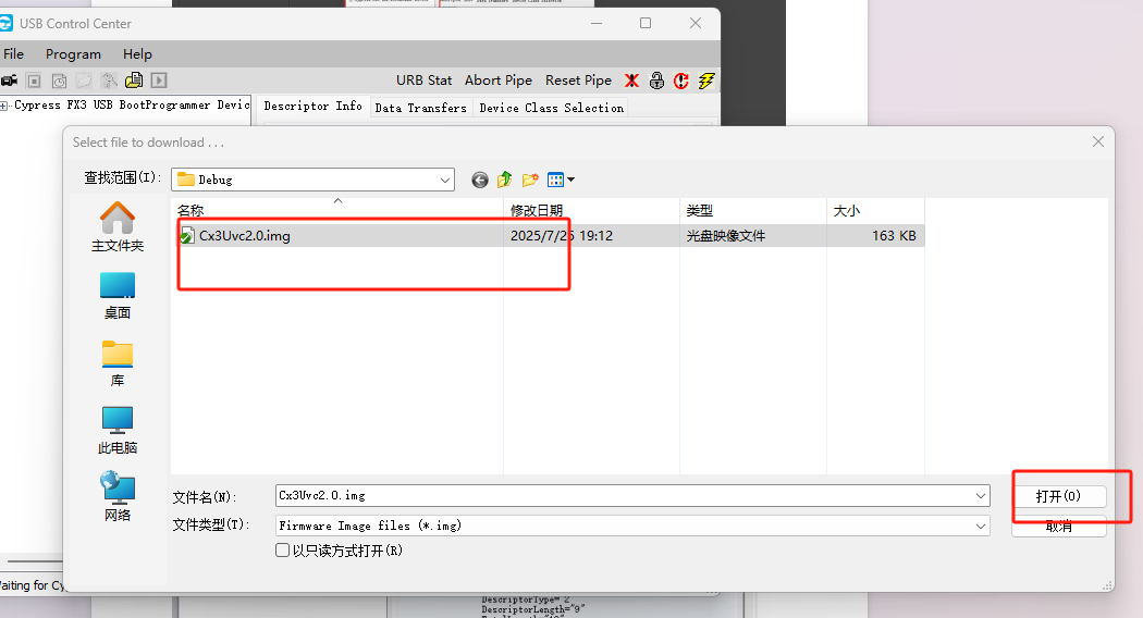
Figure 27: Firmware programming interface showing file selection and programming options with highlighted programming button
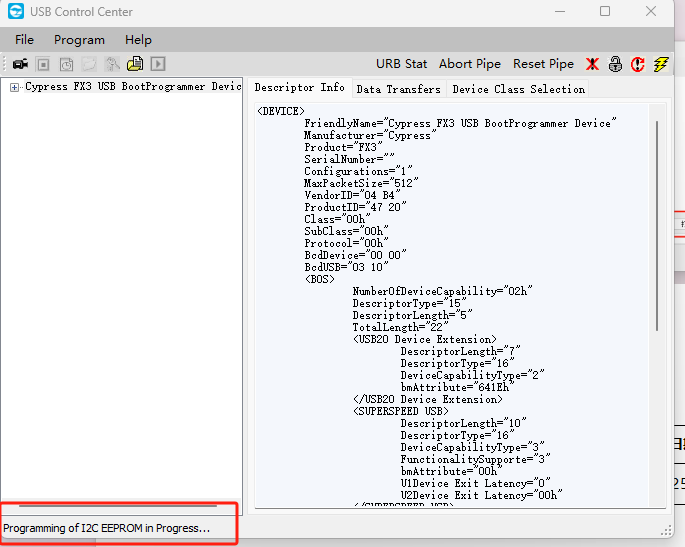
Figure 28: Programming progress display showing "Programming of I2C EEPROM in Progress..." status message
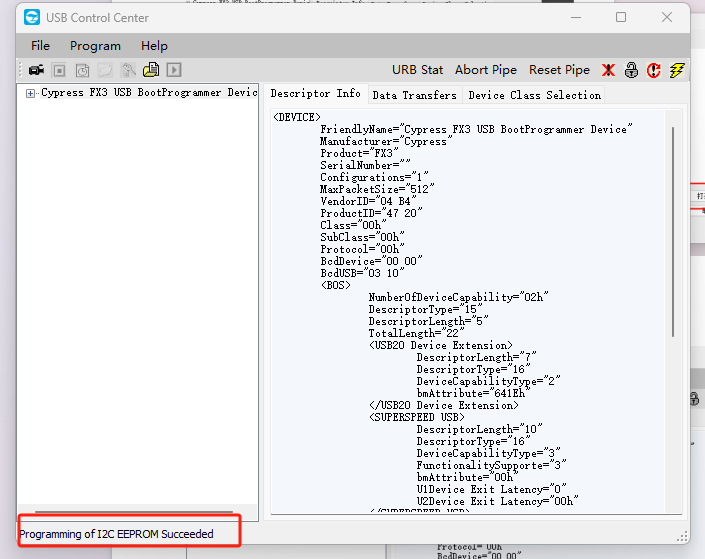
Figure 29: Programming success confirmation showing "Programming of I2C EEPROM Succeeded" status message
2.9 Linux System Configuration
In the PANDA box software package, only the point cloud is divided into 1920*1080 groups. Click on the other point cloud groups that need to be added to the configuration, configure the text and Windows configuration text files.
First, obtain the Linux configuration program.
Download link: https://github.com/SENSING-Technology/PandaCtrl
As shown in Figure 30, in the workspace interface, you can see the PandaCtrl file and libusb source file. In the program file interface, confirm that it exists in the ubuntu20.04 system's libusb library. If it exists in other systems, you need to update the libusb library, replace the generated text file, and then add the configuration text file's program.
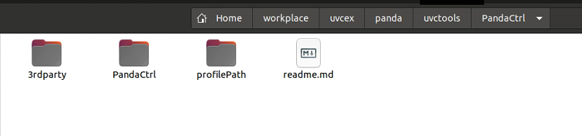
Figure 30: PandaCtrl workspace interface showing 3rdparty, PandaCtrl, profilePath, and readme.md directories
Open the PandaCtrl file and run the makefile file in the interface.
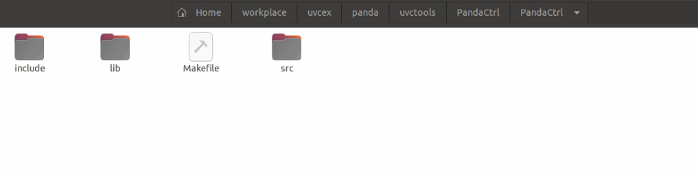
Figure 31: PandaCtrl makefile interface showing include, lib, Makefile, and src directories
After executing the makefile file, if the compilation is successful, multiple executable PandaCtrl files will be generated.
Note: You need to install gcc and make tools.
Some systems need to install some dependencies, such as ubuntu20.04 needs to execute the following commands:
sudo apt install libudev-dev
sudo apt-get install i2c-tools
2.9.1 Running Format and Command Execution
Running format: sudo ./PandaCtrl [configuration file path and name]
As shown in Figure 33, after running successfully, "Device opened successfully" indicates that the configuration file has been loaded successfully.
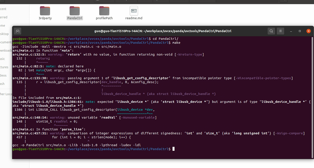
Figure 32: Terminal interface showing PandaCtrl command execution with configuration file path
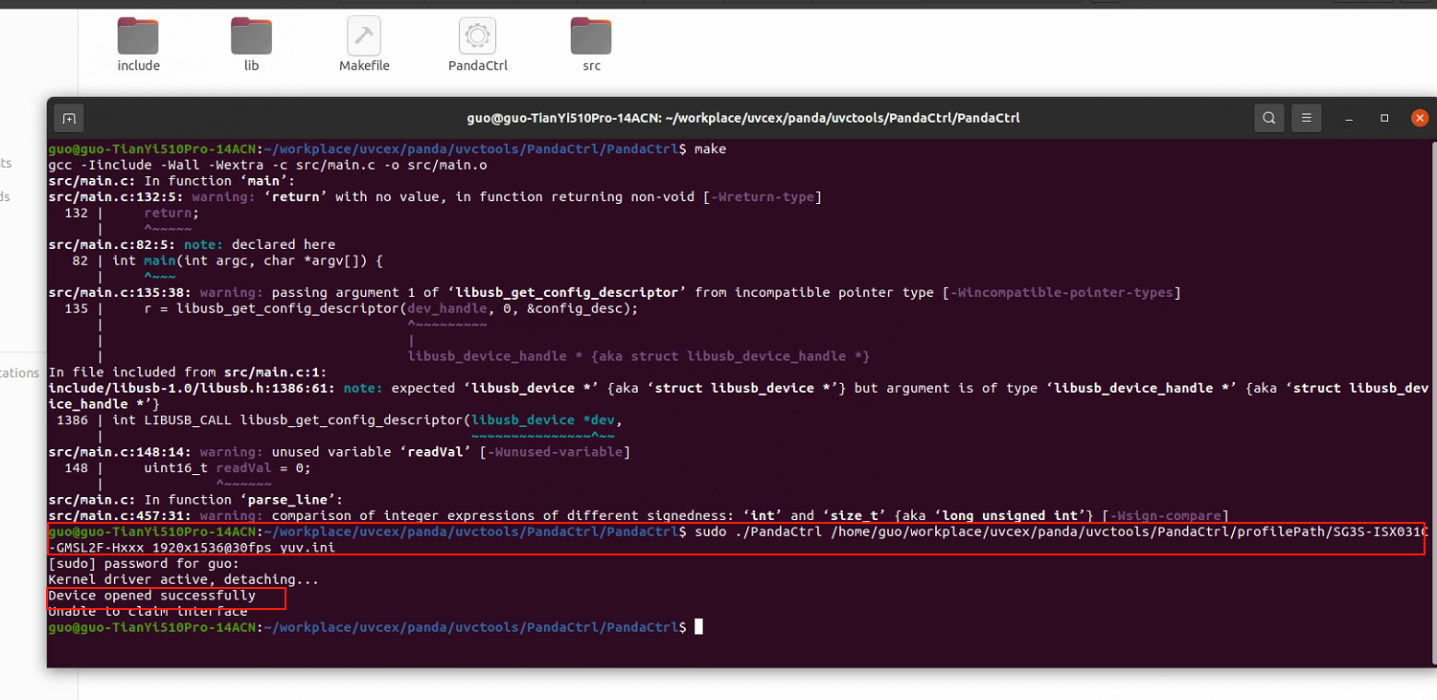
Figure 33: Terminal output showing successful device connection and configuration loading with detailed system information
2.9.2 System Compatibility and Library Requirements
After loading successfully and opening the system's printing, if the camera can be turned on normally, it indicates successful configuration. If the printing shows color mismatch, you can refer to the attached UYVY and YUYV format's corresponding relationship.
As shown in Figure 34, if you need to update the libusb library, in libusb-1.0.26 after compilation, use libusb/lib/libusb-1.0.a file to replace PandaCtrl/lib/libusb-1.0.a.
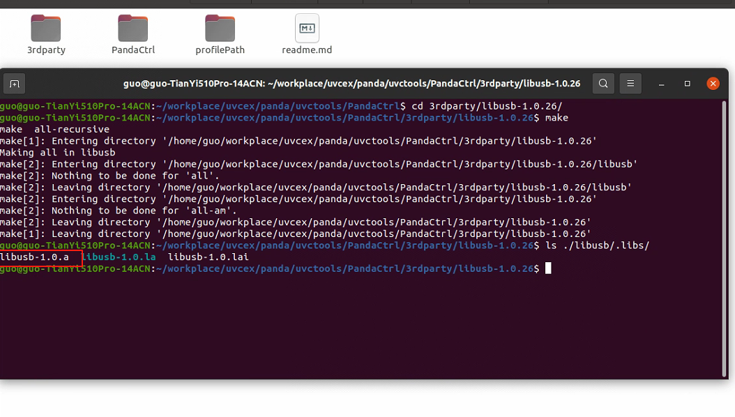
Figure 34: Terminal interface showing libusb library compilation and file replacement process for system compatibility
Important Notes:
- Ensure proper USB 3.0 connection for optimal performance
- Verify system compatibility before library updates
- Monitor terminal output for successful device recognition
- Check color format compatibility (UYVY/YUYV) if display issues occur
- Maintain proper file permissions for configuration files