CCG3-8M Application
Autonomous Driving Sensing Solution
The video capture card can be applied to the unmanned vehicle. It needs multiple cameras, millimeter wave radar, Lidar, GPS, integrated navigation and other sensors, and these sensors need to be connected to a powerful computing platform, such as an industrial personal computer. Then a product that can simultaneously connect multiple cameras and synchronize with other sensors is needed. The video capture card is to provide high-speed, multi camera, low delay image access solution for unmanned vehicle. Here are typical solution examples.
System Architecture
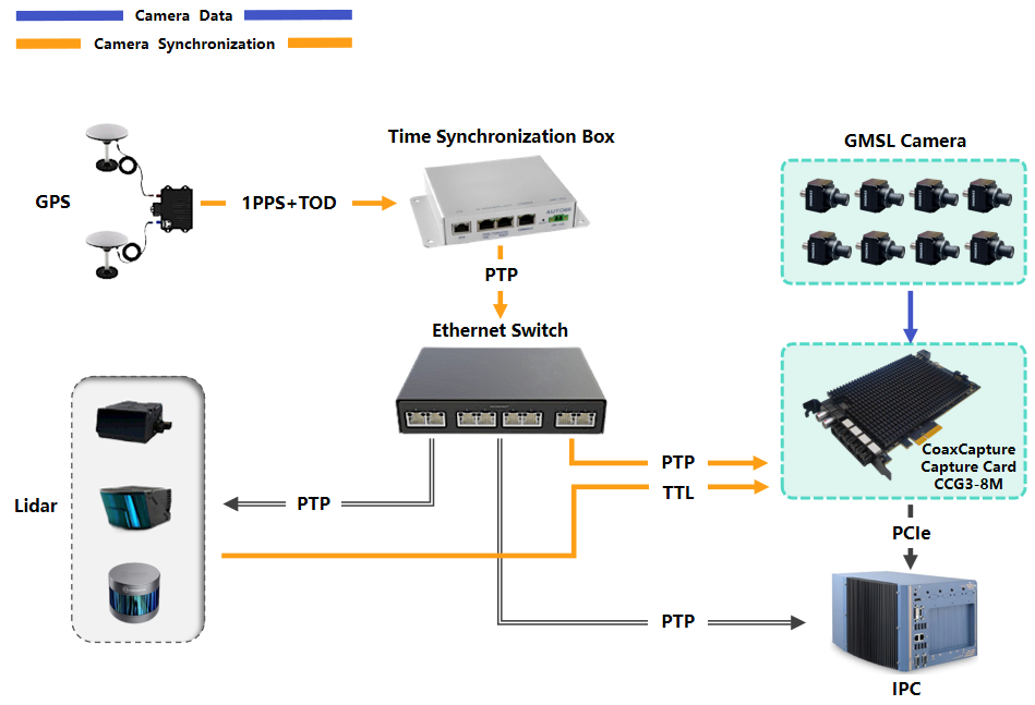
- GMSL Cameras: Multiple high-resolution cameras are connected to the CoaxCapture card, which aggregates and synchronizes their video streams.
- CoaxCapture Capture Card: Installed in the vehicle's IPC (industrial PC) via PCIe, the card receives camera data and synchronization signals, ensuring frame-level alignment across all channels.
- GPS Module: Provides 1PPS (Pulse Per Second) and TOD (Time of Day) signals for global time reference.
- Ethernet Switch: Supports PTP/gPTP (Precision Time Protocol/Generalized PTP) for time synchronization across LiDAR, radar, and other sensors.
- LiDAR/External Devices: Provide TTL square wave signals to the CCG3-8M for hardware-level camera synchronization, ensuring precise timing alignment between camera captures and sensor measurements.
- IPC (Industrial PC): Central processing unit that collects, processes, and stores synchronized data from all sensors.
Synchronization Workflow
- The GPS provides 1PPS and TOD signals to the time synchronization box, which then outputs PTP information via Ethernet to the capture cards and other devices.
- The CoaxCapture card uses these signals to synchronize all connected GMSL cameras, ensuring that each frame is timestamped accurately and aligned with other vehicle sensors.
- The Ethernet switch propagates PTP/gPTP signals to LiDAR, radar, and other devices, enabling system-wide time synchronization.
- All sensor data, including video, LiDAR, and radar, are collected by the IPC for real-time processing and recording.
Quick Bring Up
SDK Download
| Camera | Linux system version | Driver pkg download link | Driver pkg download method |
|---|---|---|---|
| GMSL2 Camera (YUV Data) (e.g.: SG3S-ISX031C-GMSL2-Hxxx) | Ubuntu 18.04/20.04/22.04/24.04 | Link | Copy the full link address to DownGit to download |
Directory Structure
The package includes the following key directories and files:
| Directory/File | Description |
|---|---|
bash/ | Bash scripts for device management. |
Makefile | Build script for drivers and applications (supports compiling per directory). |
xdma_v4l2/ | PCIe board card driver source code. |
include/ | Header files for xdma driver. |
./tool/pcie_a53_rw | Application for reading/writing data to the PCIe board's PS (Processing System). |
./tool/pcie_reg_rw | Application for reading/writing PCIe board register values. |
./tool/xdma_v4l2_rw | Application for configuring the driver via the V4L2 (Video for Linux 2) interface. |
Prerequisites
- Ubuntu 18.04, 20.04, 22.04, or 24.04.
Installation & Usage
1. Load the Driver
Enter the bash/ directory and execute the following script to load the driver:
sudo ./load_modules.sh
Successful Output:
Loading Pcie driver...
Pcie driver installed correctly.
Video devices were recognized.
DONE
Verification:
After successful loading, video device files (e.g., /dev/video0, /dev/video1, /dev/video2, /dev/video3) will be generated in the /dev directory. Control interface files (e.g., xdma0_bypass, xdma0_control, xdma0_user) will also be created. The number (e.g., 0) corresponds to the PCIe board index (e.g., 0 for the first board, 1 for the second, etc.).
2. Initialize the PCIe Board
Execute the following script to initialize the PCIe board (e.g., board 0) and configure connected cameras:
sudo ./pcie_init_card0.sh
Successful Output:
Reset Process!
Card Params Init Processed!
Serdes 0 Params Init Processed!
Serdes 1 Params Init Processed!
...
Info: All process in pcie_init.sh passed.
Note: If you have multiple capture cards, you can modify the pcie_init_card*.sh script again, and then execute the command:
sudo ./pcie_init_card*.sh
3. Image Testing
Use the open-source tool guvcview to test video capture.
Install guvcview (if not installed):
sudo apt-get install guvcview
Test Video Streams:
Connect cameras to the board, then run:
# For video0 (board 0, channel 0)
guvcview -d /dev/video0

# For video1 (board 0, channel 1)
guvcview -d /dev/video1

# Repeat for video2, video3 (if supported)
Verify Frame Rate:
To capture and verify the frame rate, execute:
v4l2-ctl -d /dev/video0 --stream-mmap --stream-count=1000
Configuring Camera Parameters
To modify parameters for different cameras, adjust:
- The
pcie_init_card0.shscript (for initialization configurations). - The
pcie_a53_rwapplication (for low-level register/control adjustments).
Firmware Programming
The capture card is pre-programmed at the factory to support YUV or RAW12 modes. To switch modes:
- Reprogram the firmware using the corresponding file from the
FirmwareResources/directory:- YUYV/UYVY (YUV): Use
pcie_zu_fw-xxxx-YUV.tar.gz. - RAW12: Use
pcie_zu_fw-xxxx-RAW12.tar.gz.
- YUYV/UYVY (YUV): Use
2.The command to upgrade the firmware of the capture card is as follows:
cd /tools/pcie_zu_tools
sudo ./pcie_zu-updata.sh ./pcie_zu_fw-xxxx-RAW12.tar.gz
Notes
- Ensure all cameras are properly connected via coaxial cables before initializing the board.
- If issues occur, check
/devdirectory for video device files and verify driver loading logs.