CCG3-8H Application
Autonomous Driving Sensing Solution
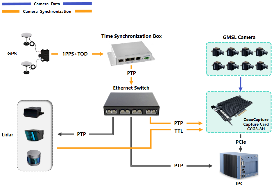
The video capture card can be applied to the unmanned vehicle. It needs multiple cameras, millimeter wave radar, Lidar, GPS, integrated navigation and other sensors, and these sensors need to be connected to a powerful computing platform, such as an industrial personal computer. Then a product that can simultaneously connect multiple cameras and synchronize with other sensors is needed. The video capture card is to provide high-speed, multi camera, low delay image access solution for unmanned vehicle. Here are typical solution examples.
System Architecture
- GMSL Cameras: Multiple high-resolution cameras are connected to the CoaxCapture card, which aggregates and synchronizes their video streams.
- CoaxCapture Capture Card: Installed in the vehicle's IPC (industrial PC) via PCIe, the card receives camera data and synchronization signals, ensuring frame-level alignment across all channels.
- GPS Module: Provides 1PPS (Pulse Per Second) and TOD (Time of Day) signals for global time reference.
- Ethernet Switch: Supports PTP/gPTP (Precision Time Protocol/Generalized PTP) for time synchronization across LiDAR, radar, and other sensors.
- LiDAR/External Devices: Provide TTL square wave signals to the CCG3-8H for hardware-level camera synchronization, ensuring precise timing alignment between camera captures and sensor measurements.
- IPC (Industrial PC): Central processing unit that collects, processes, and stores synchronized data from all sensors.
Synchronization Workflow
- The GPS provides 1PPS and TOD signals to the time synchronization box, which then outputs PTP information via Ethernet to the capture cards and other devices.
- The CoaxCapture card uses these signals to synchronize all connected GMSL cameras, ensuring that each frame is timestamped accurately and aligned with other vehicle sensors.
- The Ethernet switch propagates PTP/gPTP signals to LiDAR, radar, and other devices, enabling system-wide time synchronization.
- All sensor data, including video, LiDAR, and radar, are collected by the IPC for real-time processing and recording.
Quick Bring Up
SDK Download
| Camera | Linux system version | Driver pkg download link | Driver pkg download method |
|---|---|---|---|
| GMSL2 Camera (YUV Data) (e.g.: SG3S-ISX031C-GMSL2-Hxxx) | Ubuntu 18.04/20.04/22.04/24.04 | Link | Copy the full link address to DownGit to download |
1. Compile the driver
Before using the driver, you need to compile it. The Driver directory contains a Makefile that can build both the driver and application programs. You can either build the entire project using the top-level Makefile, or you can navigate to individual directories and compile them separately.
To build the driver:
make
If you need to clean the build directory and rebuild from scratch:
make clean
make
2. Usage Instructions
2.1 Loading the Driver
To load the driver, you need to run the script load_modules.sh with administrator privileges. In the bash directory, execute the following command:
sudo ./load_modules.sh
If the driver loads successfully, you will see the following message:
Loading Pcie driver...
Pcie driver installed correctly.
Video devices were recognized.
DONE
Additionally, video devices and control interface files will be created in the /dev directory:
/dev/video0,/dev/video1,/dev/video2,/dev/video3(video devices for each Capture card)/dev/xdma0_bypass,/dev/xdma0_control,/dev/xdma0_user(control interface devices for each Capture card)
Note: The numbers (0, 1, 2, etc.) correspond to the Capture card index. For example, xdma0_bypass corresponds to the first Capture card, xdma1_bypass to the second, and so on.
2.2 Initializing Capture Cards
To initialize the first Capture card and configure the attached camera, use the following command:
sudo ./pcie_init_card0.sh
If the script fails, you may need to rebuild the driver and applications as described earlier.
2.3 Image Testing
You can test the video stream from your camera using the open-source application guvcview. If it's not installed, you can install it with:
sudo apt-get install guvcview
To test the video streams, run the following commands for each video device:
guvcview -d /dev/video0
guvcview -d /dev/video1
You should be able to see live video from each connected camera.
3. Configuring Capture Cards
There are two example scripts in this directory: pcie_init_card0.sh and pcie_init_card1.sh. These scripts are used to initialize Capture cards and configure the attached cameras. You can modify these scripts according to your camera's specifications.
Configuration Parameters
In the configuration scripts, the following parameters can be modified to customize the behavior of the Capture cards and cameras.
3.1 Modify Card Number
In the script, the card number is specified at line 10:
set_card 0
The 0 refers to the first Capture card. Change this value to 1 for the second card, and so on.
3.2 Camera anc config
Lines 27-34 in the script configure whether the camera has ANC (Ancillary) functionality. Set 0 to enable ANC or 1 to disable it. The x refers to the interface number (0-7 for the first card, 8-15 for the second card, and so on).
camera_anc_enable[x]
3.3 Image Output Format
"The lines 38-45 correspond to the camera output format. RAW can be ignored, and incorrect configuration of YUYV or UYVY may cause image display issues.
The first parameter (shown as 0 below) indicates which interface to use. For the first Capture capture card, channels 1 to 8 correspond to 0-7, and for the second Capture capture card, channels 1 to 8 correspond to 8-15.
The second parameter specifies the camera's output image format, which can be either 'YUYV' or 'UYVY'."
video_output_yuv_format 0 "UYVY"
3.4 Trigger Mode
Configure the trigger mode in the script. The options are:
0: No trigger (master mode only, no external trigger needed).1: Reserved.2: Internal trigger (PCIE card triggers the camera at a specified frequency).3: External trigger (triggered by an external signal).
card_trigger_signal_mode "2"
3.5 External Trigger Configuration
If you use an external trigger, configure the following parameters:
card_external_signal_input_fps 	"1" Hz
camera_external_output_fps     	"30" Hz
3.6 Internal Trigger Configuration
When the card_trigger_signal_mode parameter is set to "2", the frequency of the internally generated trigger signal is configured through the camera_inner_output_fps on line 66, with the unit in Hz
camera_inner_output_fps "30" Hz
3.7 Trigger Delay
You can set the trigger delay for each camera:
camera_triger_delay[x]=0
3.8 Camera Resolution
Configure the resolution for each camera interface (e.g., for interface 0, set a resolution of 1920x1080):
camera_resolution 0 1920 1080
3.9 Camera Initialization
The camera_serdes_type parameter initializes the camera sensor, serializer, and deserializer. For example:
camera_serdes_type[0]=1
Common YUYV or UYVY Configurations
| Serializer | ANC | Configuration Parameter |
|---|---|---|
| MAX96705 | no | 0 |
| MAX9295 | no | 1 |
| MAX96717F | no | 2 |
| MAX9295 | yes | 3 |
| MAX96717F | yes | 4 |
Common RAW or RAW12 Configurations
| Serializer | Sensor Model | Configuration Parameter |
|---|---|---|
| MAX9295 | AR0233 | 102 |
| MAX9295 | AR0820 | 103 |
| MAX9295 | IMX390 | 104 |
| MAX9295 | IMX490 | 105 |
| MAX9295 | ISX031 | 11 |
| MAX9295 | IMX728 | 106 |
| MAX9295 | SC2331AT | 108 |
| MAX9295 | OX08D | 109 |
| MAX96717F | IMX623 | 113 |
This architecture is ideal for autonomous driving, ADAS development, and any application requiring precise, synchronized multi-sensor data acquisition.